Using Events, Logic, And IR
9 - 19
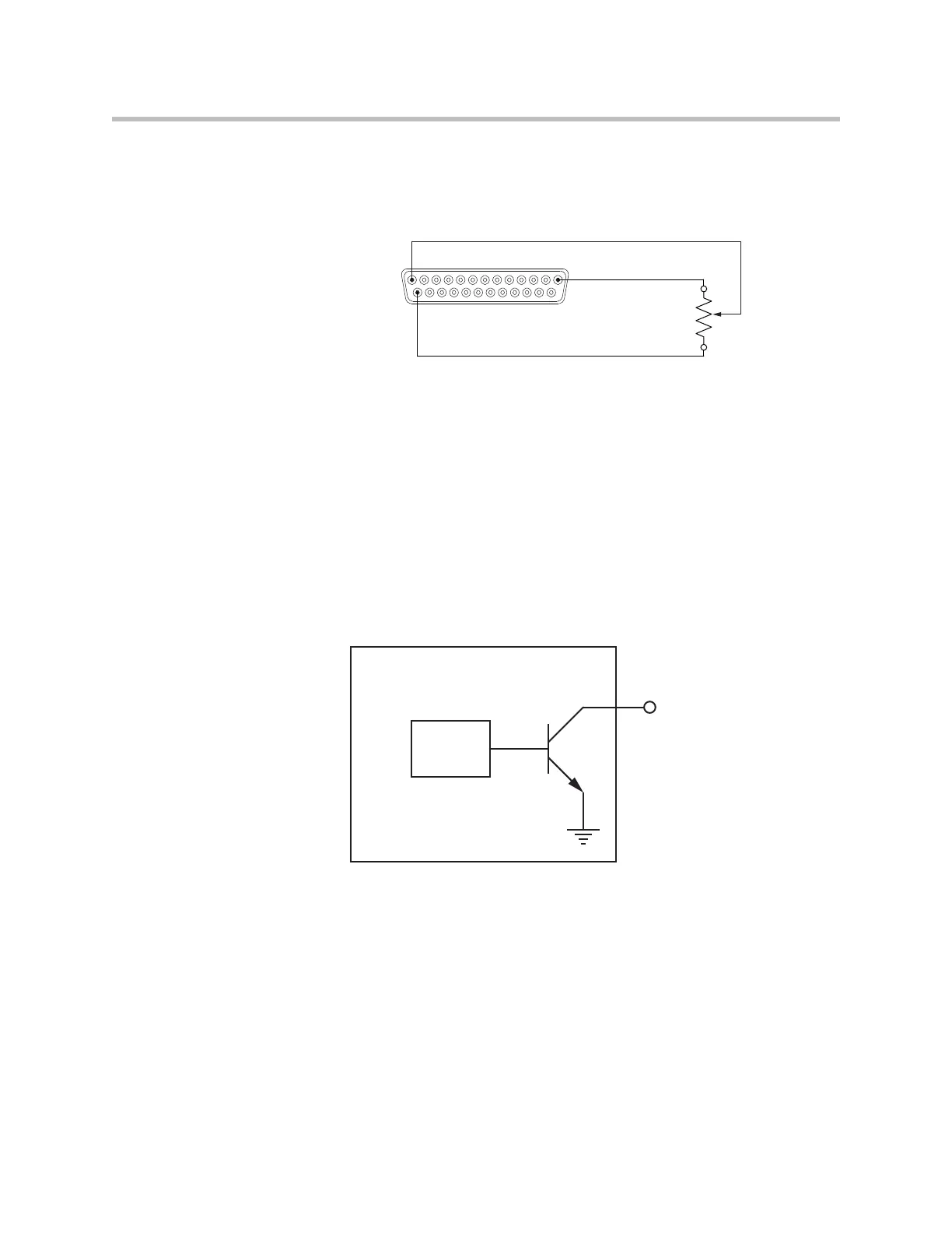
knob is turned, the voltage measured will vary between 0 and approximately
5V. The values measured from the analog logic gain input will vary from
approximately 0 to 255.
Logic Outputs
SoundStructure devices implement logic outputs as open collector circuits.
The open collector design, shown in the following figure, makes it possible to
drive LED’s and relays with minimal additional circuitry. Please note that only
positive external voltages, such as the +5V supply on pin 1, should be used
with the logic output pin.
Each logic output pin is capable of sinking 60mA of current.
If using an external voltage supply as part of any logic output circuit, the max-
imum voltage that should be used with the logic outputs is 60V with a
maximum current of 500 mA.
Remote Control
Pin 1 : +5V
Pin 13 : Analog Input
Pin 25 : Ground
10K ohm
Logic
Controller
SoundStructure Logic Output
Logic Output Pin
Chassis
Ground

 Loading...