Surveillance Systems
(Video Cameras)
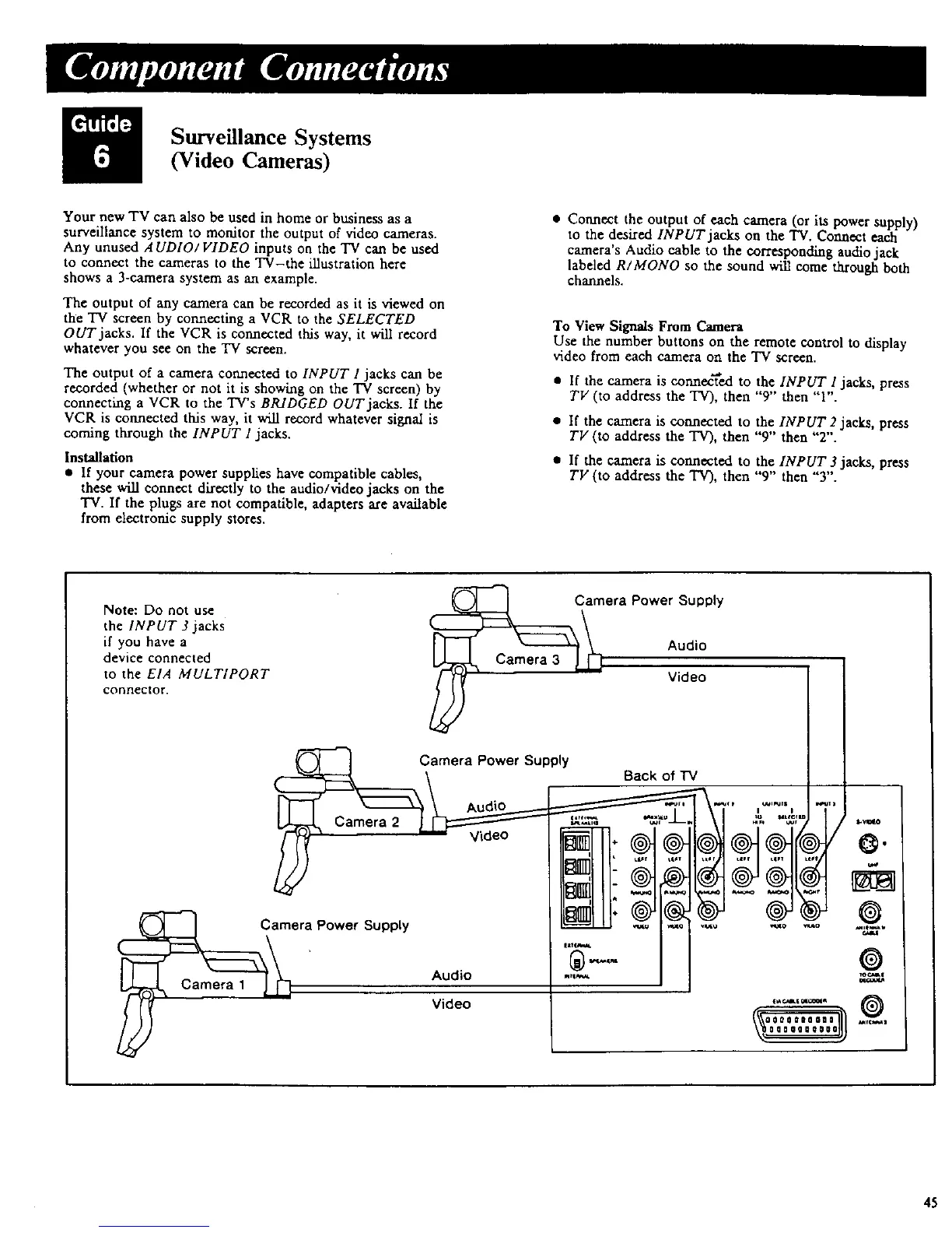
Your new TV can also be used in home or business as a
surveillance system to monitor the output of video cameras.
Any unused AUDIO/ VIDEO inputs on the TV can be used
to connect the cameras to the TV-the illustration here
shows a 3-camera system as an example.
The output of any camera can be recorded as it is viewed on
the "IV screen by connecting a VCR to the SELECTED
OUT jacks. If the VCR is connected this way, it will record
whatever you see on the "IV screen.
The output of a camera connected to INPUT 1 jacks can be
recorded (whether or not it is showing on the TV screen) by
connecting a VCR to the TV's BP-dDGED OUT jacks. If the
VCR is connected this way, it will record whatever signal is
coming through the INPUT 1 jacks.
Installation
• If your camera power supplies have compatible cables,
these will connect directly to the audio/video jacks on the
TV. If the plugs are not compatible, adapters axe available
from electronic supply stores.
• Connect the output of each camera (or its power supply)
to the desired INPUT jacks on the TV. Connect each
camera's Audio cable to the corresponding audio jack
labeled R/MONO so the sound will come through both
channels.
To View Signals From Camera
Use the number buttons on the remote control to display
video from each camera on the TV screen.
• If the camera is connected to the INPUT I jacks, press
TV (to address the TV), then "9" then "1".
• If the camera is connected to the INPUT 2 jacks, press
TV (to address the TV), then "9" then "2".
• If the camera is connected to the INPUT 3 jacks, press
TV (to address the TV), then "9" then "3".
Note: Do not use
the INPUT 3 jacks
if you have a
device connected
to the EIA MULTIPORT
connector.
C_era Power Supply
Audio
Video
Camera Power Supply
Back of "IV
\ AudiO _..__.- _ ["_'_" ,..... ,"7"
L_ Carnera2 __ _______,. _ .............. _)'
Camera wower _,uppty _ _ [_o .......
' Audio "_--='_"_ J '*_'
45
 Loading...