Renesas RA Family RA4 Quick Design Guide
R01AN5988EU0100 Rev.1.00 Page 10 of 51
Jul.21.21
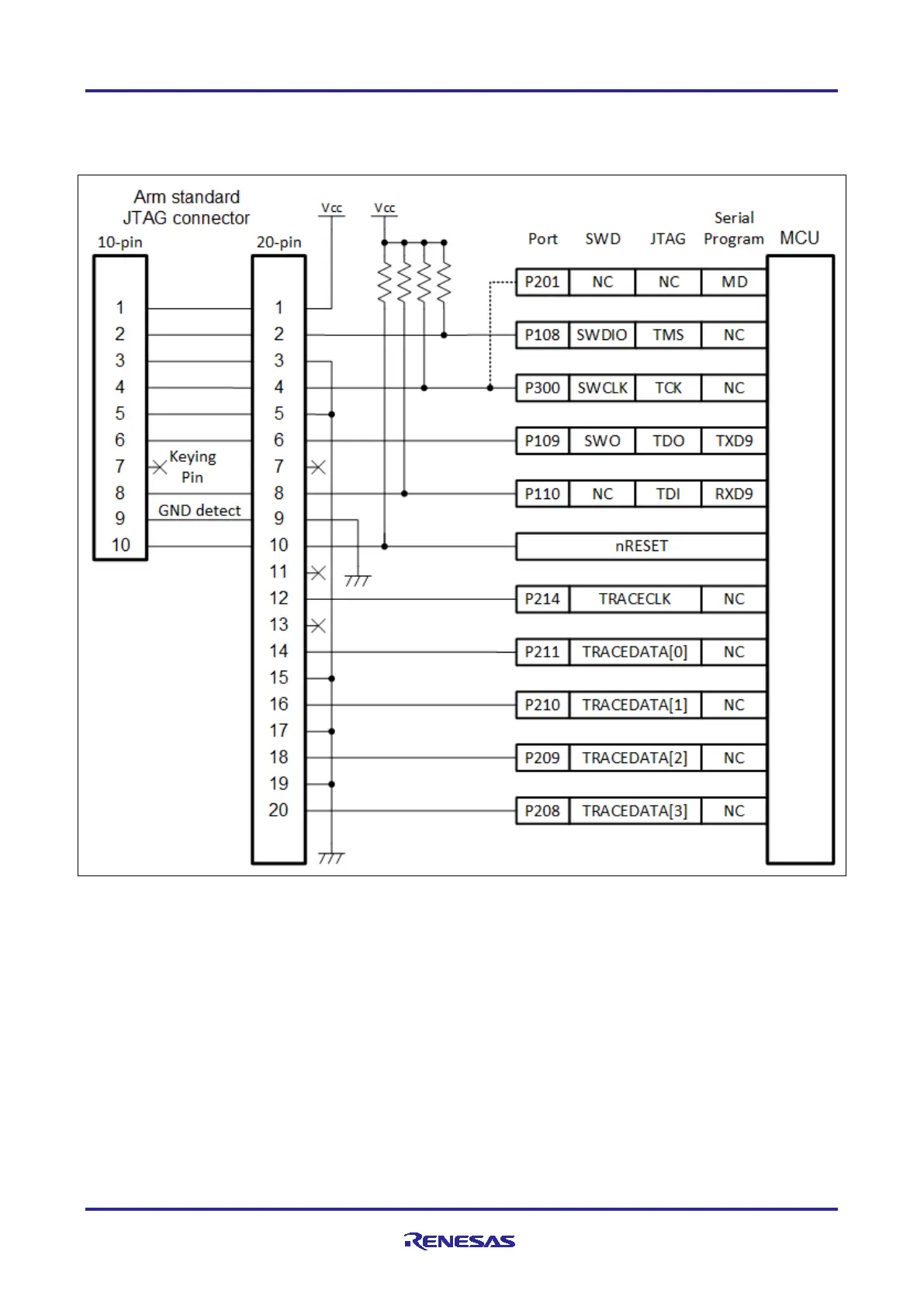
2.5 Multiple Emulator Interface
The following diagram shows the typical connectivity of the debug interface to support multiple emulator
types, including SWD, JTAG, SCI Serial Programming, and TrustZone support.
Figure 5. Multiple Emulator Interface Connections
Notes: 1. Reset circuitry on the target must be open-collector. Pull up the nRESET signal. Do not put a
capacitor on this signal as it may affect the operation of the power-on reset circuit.
2. Use 4.7-kΩ to 10-kΩ pull-ups on TMS, TCK, and TDI.
3. To use both debugging and serial programming on devices with TrustZone support,
connect P201/MD to P300/SWCLK/TCK using a wired OR circuit.
4. Arm Cortex-M4 devices, such as RA4M1, do not support the TRACECLK or TRACEDATA[n] pins.

 Loading...


