Renesas RA Family RA4 Quick Design Guide
R01AN5988EU0100 Rev.1.00 Page 6 of 51
Jul.21.21
2.1 SWD Interface
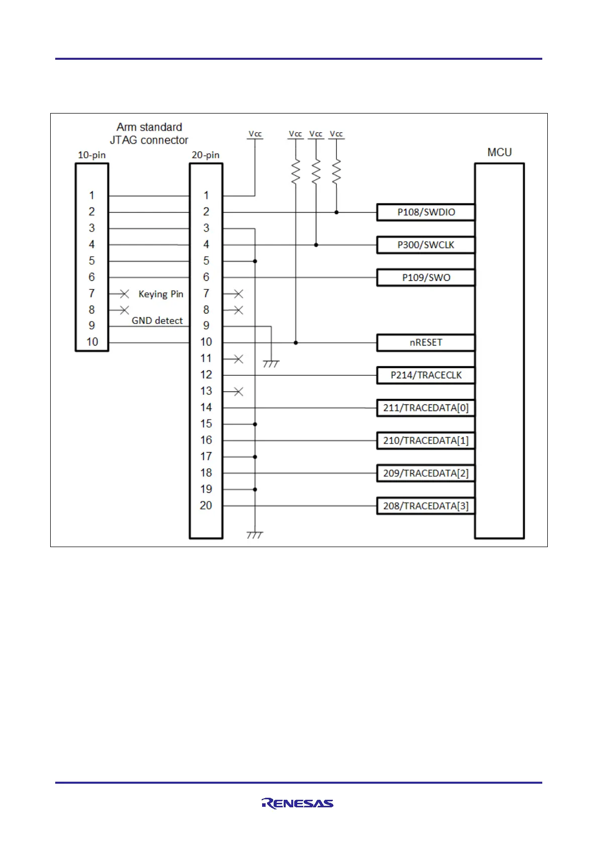
The following diagram shows the typical connectivity of the debug interface when using Serial Wire Debug
(SWD).
Figure 1. SWD Interface Connections
Note: 1. The output of the reset circuit of the user system must be open collector.
2. Arm Cortex-M4 devices, such as RA4M1, do not support the TRACECLK or TRACEDATA[n] pins.

 Loading...


