Renesas RA Family RA4 Quick Design Guide
R01AN5988EU0100 Rev.1.00 Page 20 of 51
Jul.21.21
When a crystal resonator is used, place the resonator and its load capacitors as close to the MCU clock pins
(XTAL/EXTAL, XCIN/XCOUT) as possible. Avoid routing any other signals between the crystal resonator and
the MCU. Minimize the number of connecting vias used on each trace.
5.9 External Crystal Resonator selection
An external crystal resonator may be used as the main clock source. The external crystal resonator is
connected across the EXTAL and XTAL pins of the MCU. The frequency of the external crystal resonator
must be in the frequency range of the main clock oscillator.
Selection of a crystal resonator will be largely dependent on each unique board design. Due to the large
selection of crystal resonators available that may be suitable for use with RA4 MCU devices, carefully
evaluate the electrical characteristics of the selected crystal resonator to determine the specific
implementation requirements.
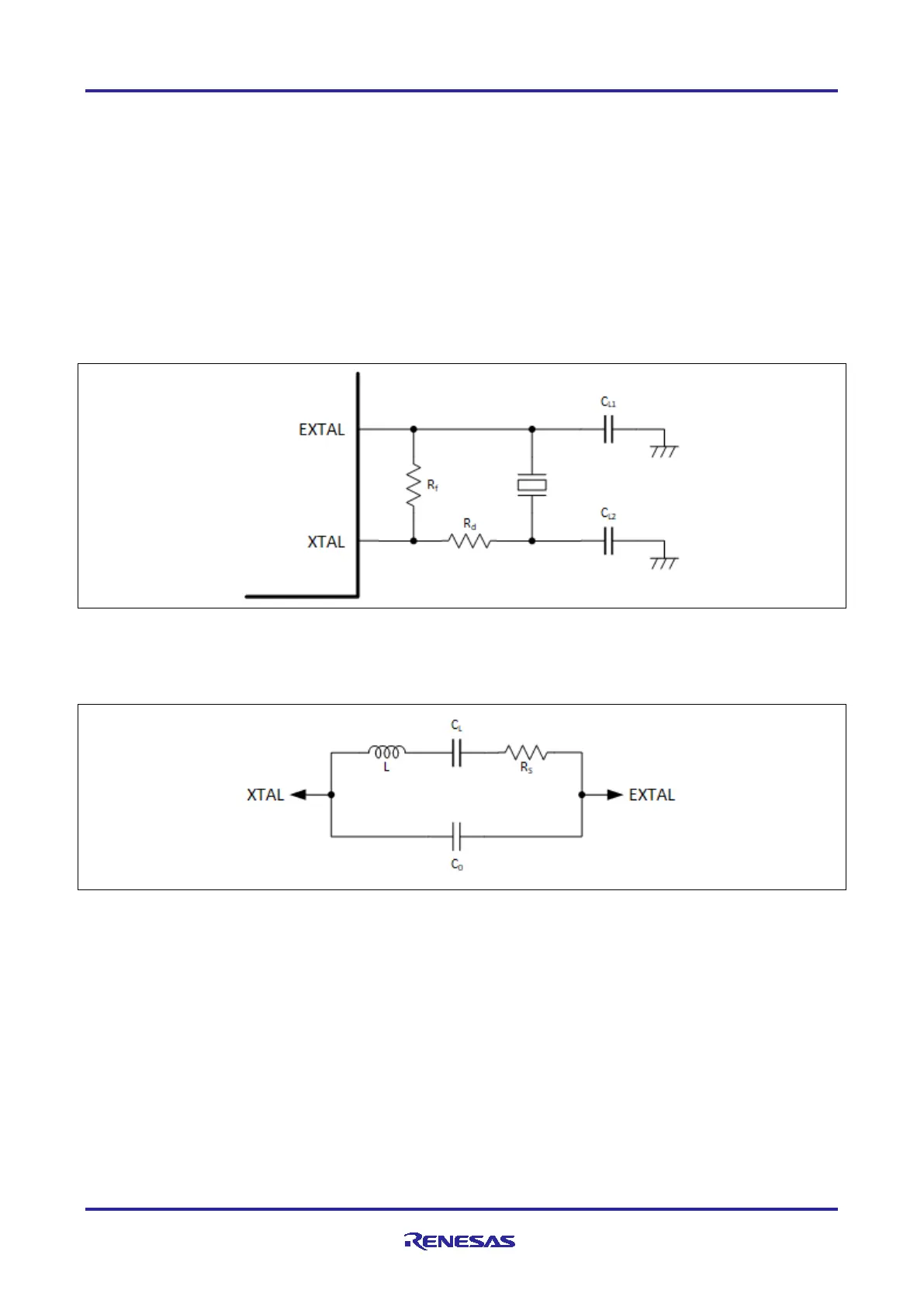
The following diagram shows a typical example of a crystal resonator connection.
Figure 13. Example of Crystal Resonator Connection
Careful evaluation must be used when selecting the crystal resonator and the associated capacitors. The
external feedback resistor (R
f
) and damping resistor (R
d
) should be added if recommended by the crystal
resonator manufacturer.
Figure 14. Equivalent Circuit of the Crystal Resonator
Selection of the capacitor values for CL1 and CL2 will affect the accuracy of the internal clock. To
understand the impact of the values for CL1 and CL2, the circuit should be simulated using the equivalent
circuit of the crystal resonator in the figure above. For more accurate results, also take in to account the stray
capacitance associated with the routing between the crystal resonator components.
5.10 External Clock Input
A digital clock input may be used as the main clock source. Figure 15 shows an example of connecting an
external clock input. To operate the oscillator with an external clock signal, set the MOMCR.MOSEL bit to 1.
The XTAL pin becomes high impedance.

 Loading...


