Renesas RA Family RA4 Quick Design Guide
R01AN5988EU0100 Rev.1.00 Page 38 of 51
Jul.21.21
10.3 Setting Up and Using Port Peripheral Functions
The Port mn Pin Function Select Registers (PmnPFS) are used to configure the characteristics of each port.
The PSEL bits select the peripheral function selected for each port.
• Since most pins have multiple functions, the RA4 MCUs have Pin Function Control Registers (PmnPFS)
that allow you to change the function assigned to a pin.
• Each pin has its own PmnPFS register.
• Each PmnPFS register allows a pin to be used for peripheral function (PSEL bits), as an IRQ input pin
(ISEL bit), or as an analog input pin (ASEL bit). If the ASEL bit is set to “1” (use pin as analog input pin)
then the pin’s PMR bit should be set for GPIO use and the pin’s PDR bit should be set for input.
• Refer to the “Peripheral Select Settings for each Product” section in the “I/O Ports” chapter of the
Hardware User’s Manual.
• In order to ensure that no unexpected edges are input or output on peripheral pins, make sure to clear
the Port Mode Control (PMR) bit for the targeted pin before modifying the pin’s PmnPFS register.
• All PmnPFS registers are write protected after reset. In order to write to these registers, the Write-Protect
Register (PWPR) must first be used to enable writing.
• Care should be taken when setting PmnPFS registers such that a single function is not assigned to
multiple pins. The user should not do this but the MCU will allow it. If this occurs the function on the pins
will be undefined.
• If you are using the external bus, the Ethernet controller, or USB, there are additional registers in the
MPC that must be configured before using these peripherals.
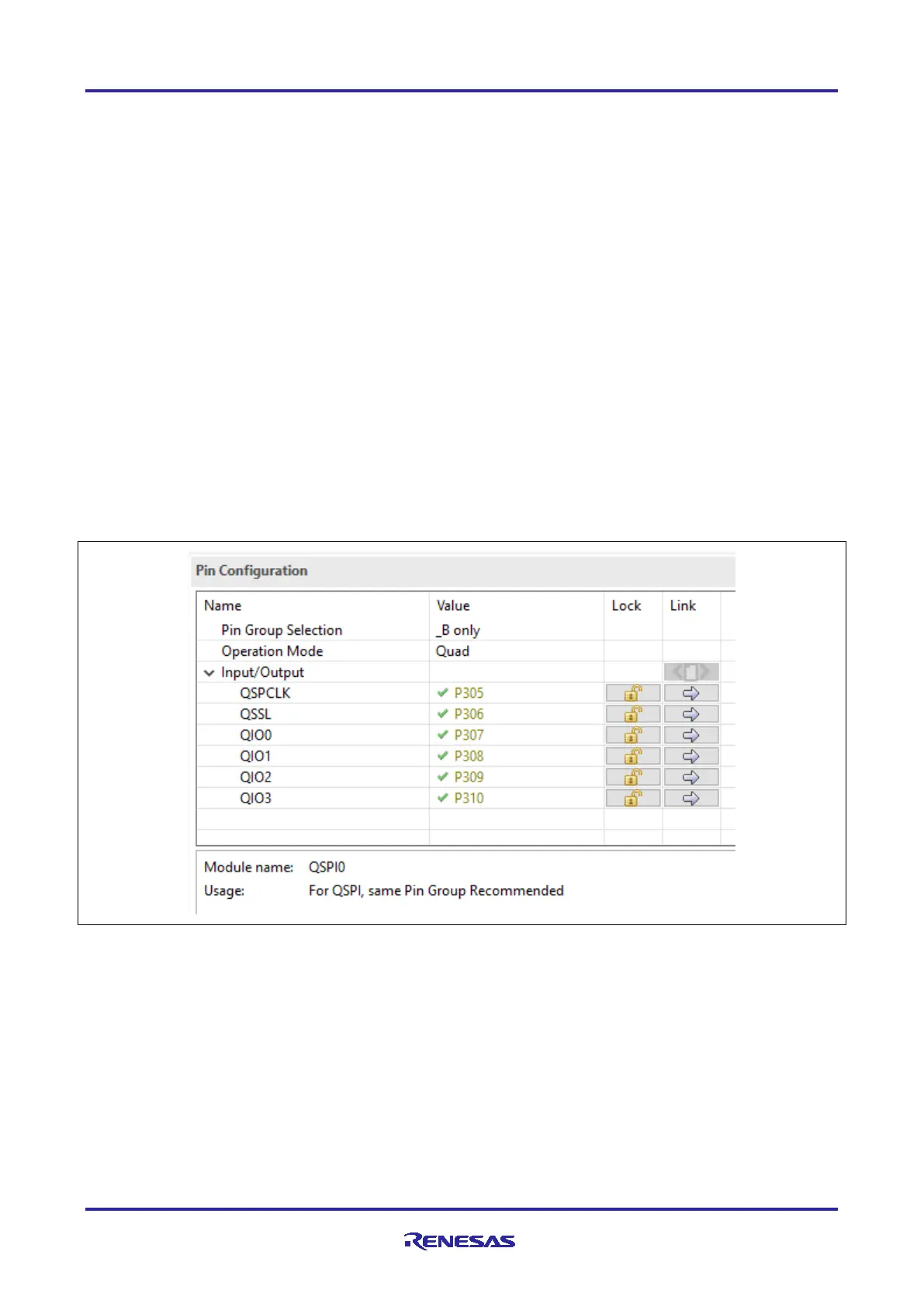
• The figure below shows an example of enabling QSPI pins using FSP Pin configuration.
Figure 29. Enabling QSPI pins Using Pin Configurator in Renesas FSP

 Loading...


