Renesas RA Family RA4 Quick Design Guide
R01AN5988EU0100 Rev.1.00 Page 36 of 51
Jul.21.21
10.2 Setting Up and Using a Pin as GPIO
There are two methods for setting up and using a pin as GPIO, either using the Port Control Register
(PCNTR1), or the PmnPFS registers.
Method 1: Port Control Register (PCNTR1)
• Select a pin as an output by writing a “1” to the Port Direction bit (PDRn) in Port Control Register 1
(PCNTR1).
• The Port Direction bits (PDRn) are read/write. Setting the value to a “1” selects the pin as an output.
Default state for I/O Ports is “0” (input). The port direction registers can be read on the RA4 MCUs.
• The Port Output Data bits (PODRn) in the corresponding Port Control Register (PCNTR1) are read/write.
When the PODR is read the state of the output data latch (not the pin level) is read.
• The Port Input bits (PIDRn) in Port Control Register 2 (PCNTR2) are read only. Read the PIDRn bit in the
PCNTR2 register to read the pin state.
Method 2: Port mn Pin Function Select (PmnPFS) registers
• The Port Mode Register (PMR) is read/write and is used to specify whether individual pins function as
GPIO or as peripheral pins. Just after reset, all PMR registers are set to 0, which sets all pins to work as
GPIO. If a PMR register is set to 1 then that corresponding pin will be used for peripheral functions. The
peripheral function is defined by that pin’s MPC setting.
• When setting a pin as an output, it is recommended that the desired output value of the port be written to
the data latch first, then the direction register is set to an output. Though not important in all systems, this
prevents an unintended output glitch on the port being set up.
In general, using PCNTR1 to configure a port will provide faster access but will have fewer configuration
features available. Using the PmnPFS registers will have more configuration features available but will have
slower access.
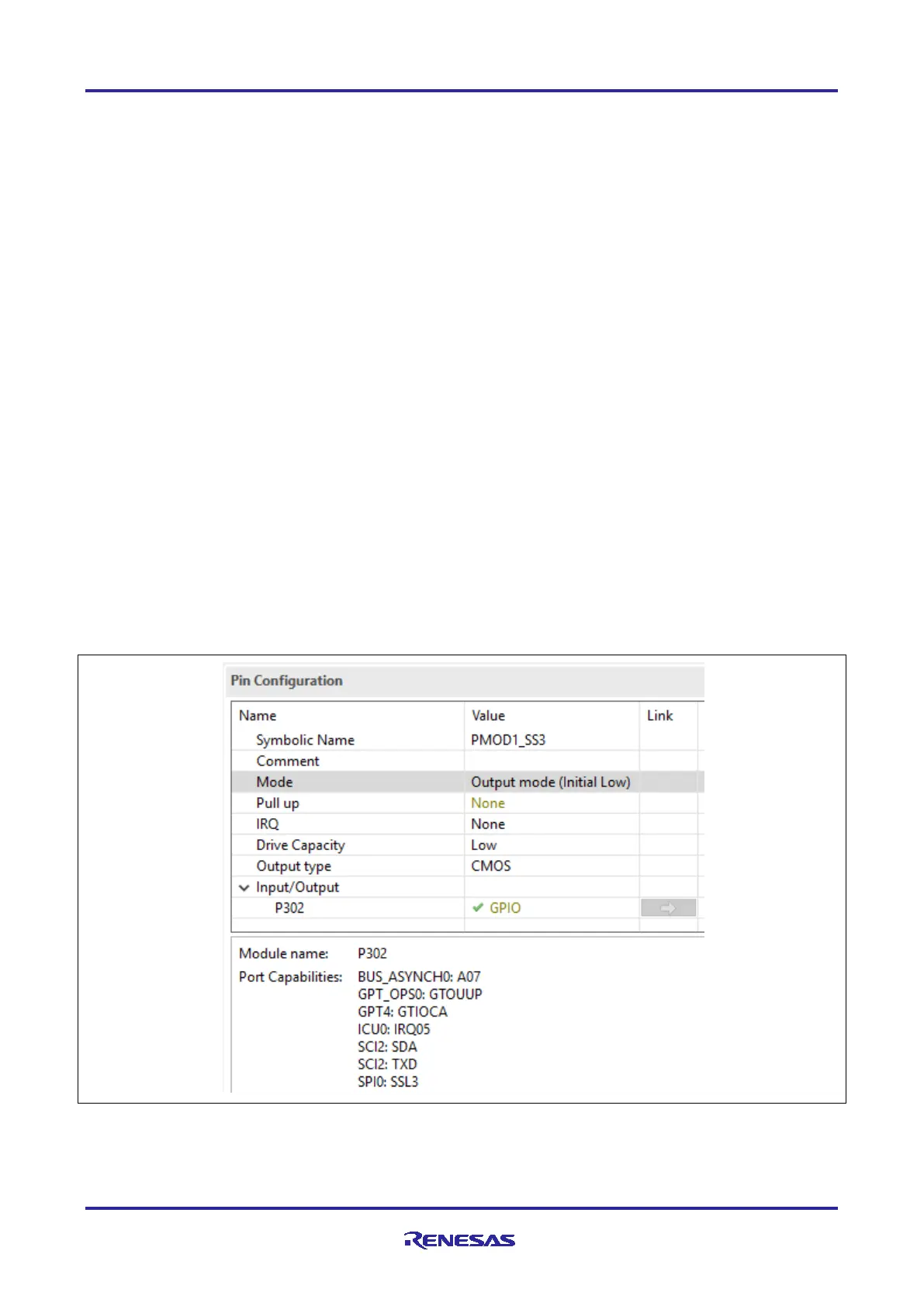
The Renesas FSP provides a Pin Configurator to configure GPIO pins after reset as shown below. After the
GPIO is configured, it can be controlled using HAL layer APIs in FSP.
Figure 28. Configuring P302 as Output and Low using FSP Configurator

 Loading...


