Renesas RA Family RA4 Quick Design Guide
R01AN5988EU0100 Rev.1.00 Page 4 of 51
Jul.21.21
1. Power Supplies
The RA family has digital power supplies and analog power supplies. The power supplies use the following
pins.
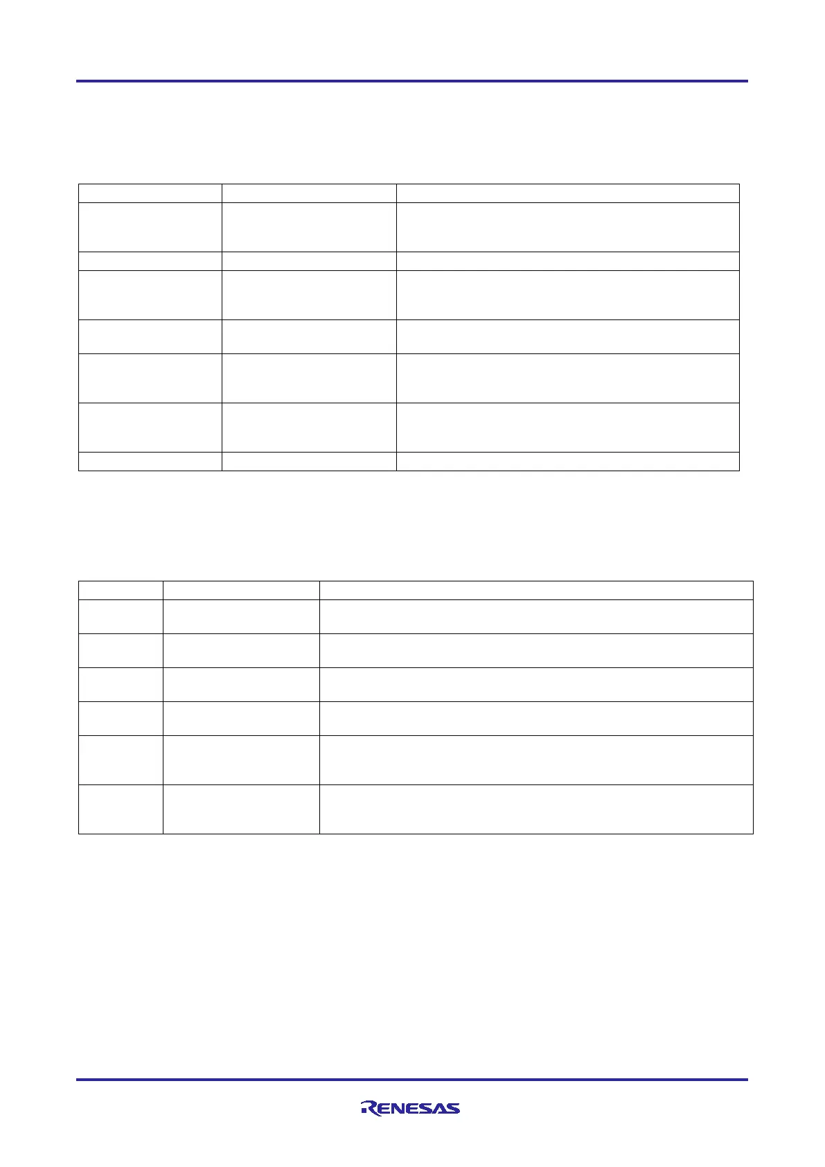
Table 1. Digital Power Supplies
Power supply pin. Connect to the system power
supply. Connect this pin to VSS via a 0.1-µF
capacitor placed close to the VCC pin.
Connect this pin to VSS via a capacitor close to the
VCL pin. The value depends upon the specific MCU
Group.
Connect this pin to VSS via a 0.1-µF capacitor close
to the VCL0 pin.
Backup power pin. Supplies power to RTC and sub-
clock oscillator in the absence of VCC. When VBATT
pin is not used, connect to VCC or VSS.
USB Full-speed power supply pin. Connect this pin to
VCC. Connect this pin to VSS_USB via a 0.1-µF
capacitor placed close to the VCC_USB pin.
USB Full-speed ground pin. Connect this pin to VSS.
Note 1: For RA4M1, VCC_USB can be either input or output. As input, it is the supply voltage for the USB
transceiver. As output it is the voltage out from the USB LDO Regulator, and needs an external
capacitor. When the USB LDO Regulator is not used, connect to VCC. When the regulator is used,
connect to VSS through a 1.0-µF capacitor.
Table 2. Analog Power Supplies
Analog voltage supply pin for the respective modules. Connect this
pin to the same voltage as the VCC pin.
Analog ground for the respective modules. Connect this pin to the
same voltage as the VSS pin.
reference voltage
Reference voltage input pin for the 12-bit A/D. Connect this pin to
AVCC0 if the 12-bit A/D converter is not used.
reference voltage
Analog reference ground pin for the 12-bit A/D converter. Connect
this pin to VSS if the 12-bit A/D converter is not used.
analog supply
Reference voltage input pin for the 12-bit A/D converter, unit 1 (if
present) and the D/A converter. Connect this pin to AVCC0 if these
features are not used.
analog ground
Reference ground pin for the 12-bit A/D converter, unit 1 (if present)
and the D/A converter. Connect this pin to VSS if these features are
not used.
Note 1. For RA4M1, this applies to the 14-bit ADC.
1.1 References
Further information regarding the power supply for the RA MCU Group can be found in the following
documents:
• R01UH0887 RA4M1 Group, RA4M1 Group User’s Manual: Hardware
• R01UH0892 RA4M2 Group, RA4M2 Group User’s Manual: Hardware
• R01UH0893 RA4M3 Group, RA4M3 Group User’s Manual: Hardware
Chapter numbers may vary between Arm
®
Cortex
®
-M4 and Arm
®
Cortex
®
-M33 devices.
Chapter 1, “Overview”, lists power pins in each package with recommended bypass capacitors.

 Loading...


