Renesas RA Family RA4 Quick Design Guide
R01AN5988EU0100 Rev.1.00 Page 39 of 51
Jul.21.21
10.4 Setting Up and Using IRQ Pins
• Certain port pins can be used as hardware interrupt lines (IRQ). See the “Peripheral Select Settings for
each Product” section in the “I/O Ports” chapter of the Hardware User’s Manual for information on which
pins are available for your MCU.
• Some IRQ pins have a “-DS” suffix (e.g. IRQ1-DS). The “-DS” designates that this pin can be used to
wake the MCU out of deep software standby mode.
• Note: It is not possible to use IRQn and IRQn-DS at the same time. Same number interrupts with the -DS
and without the -DS suffix connect to the same interrupt internally, even though they use different external
pin connections.
• To set a port pin to be used as an IRQ pin, the Interrupt Input Function Select bit (ISEL) in the pin’s PFS
register must be set to “1”.
• Pins can be used for both IRQ and peripheral functions simultaneously. To enable this the user should
set both the ISEL and PSEL bits in the pin’s PFS register.
• IRQ functions of the same number must only be enabled on one pin.
• IRQ pins can trigger interrupts on detection of:
Low level
Falling edge
Rising edge
Rising and falling edges
Which trigger is selected is chosen using the IRQ Control Registers (IRQCRi).
• Digital filtering is available for IRQ pins. The filters are based on repetitive sampling of the signal at one of
four selectable clock rates (PCLK, PCLK/8, PCLK/32, PCLK/64). They filter out short pulses: any high or
low pulse less than 3 samples at the filter rate. The filters are useful for filtering out ringing and noise in
these lines but are much too quick for filtering out long events like mechanical switch bounce. Enabling
filtering adds a short bit of latency (the filter time) to the hardware IRQ lines.
• Digital filtering can be enabled for each IRQ pin independently. This is done by setting the IRQ Pin Digital
Filter Enable (FLTEN) bit in the IRQCRi register for each IRQ.
• The clock rate for digital filtering is configurable for each IRQ pin independently. This is done by setting
the IRQ Pin Digital Filter Setting (FCLKSEL[1:0]) bits in the IRQCRi register for each IRQ.
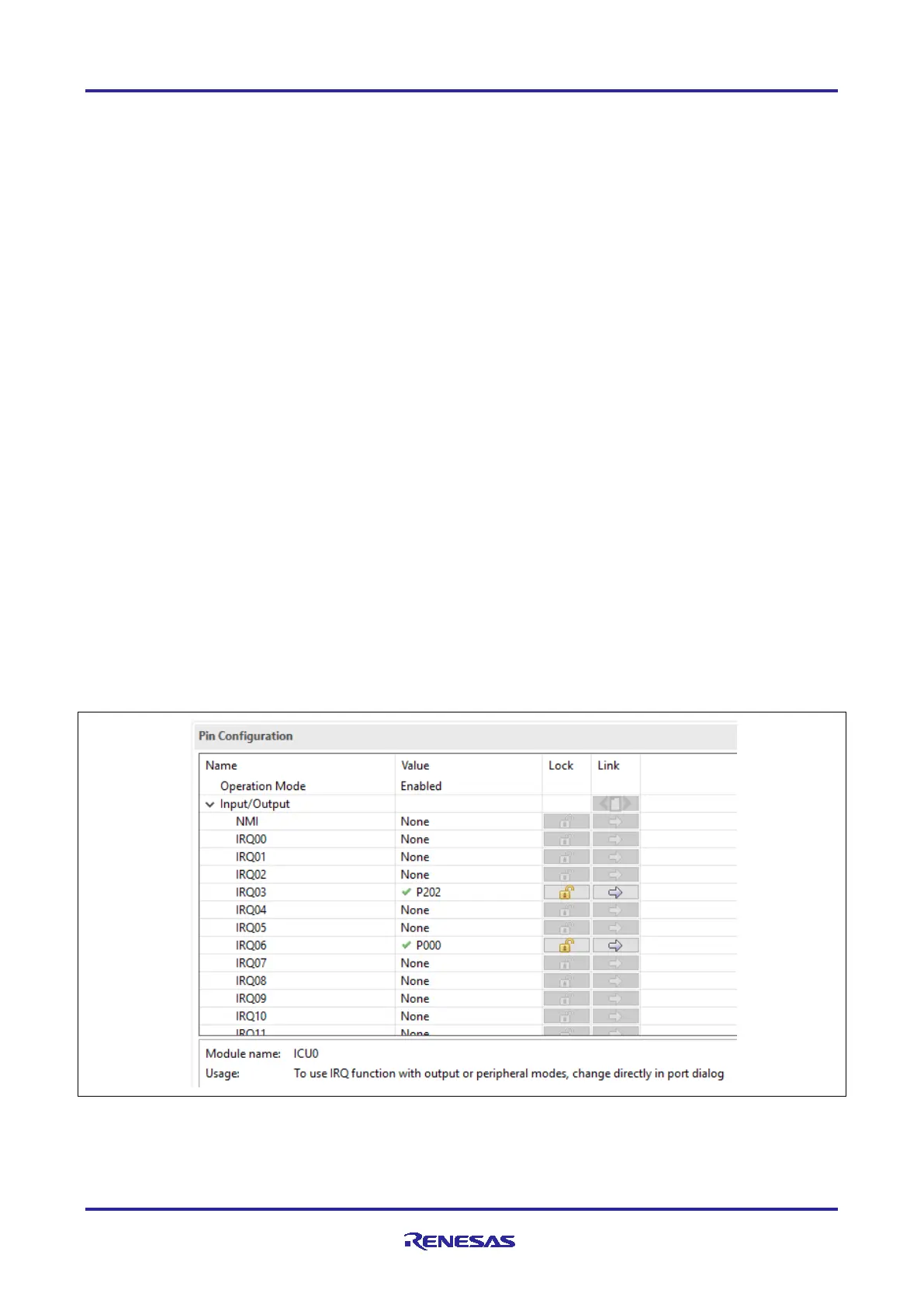
• Figure 30 and Figure 31 show examples of enabling and configuring IRQ pins using Renesas FSP.
Figure 30. Enable P202, P000 as IRQ03, IRQ06 Inputs Respectively Using Pin Configurator in
Renesas FSP

 Loading...


