Renesas RA Family RA4 Quick Design Guide
R01AN5988EU0100 Rev.1.00 Page 11 of 51
Jul.21.21
2.6 Software Setups for Emulator Connections
2.6.1 SWD and JTAG Interfaces
SWD and JTAG pins are in default state after reset. Table 4 shows the associated pins and their default
settings after reset.
Table 4. SWD/JTAG Pins
2.6.2 Trace Port
A 4-bit Trace Port Interface Unit (TPIU) and Serial Wire Output (SWO) provide trace output in RA4 devices.
Trace ports and clock need to be enabled before they can be used by the debugger script. When using the
Trace Port functionality, avoid using the trace pins for other functions.
Table 5 lists the Trace Port pins and their associated functions.
Table 5. Trace Ports
Arm Cortex-M4 devices, such as RA4M1, do not support the TRACECLK or TRACEDATA[n] pins. For these
devices, trace data is available through the SWO pin.
For an example of using the Trace Port on Arm Cortex-M33 core devices with SEGGER J-Trace Pro, refer
to the following link:
https://wiki.segger.com/RA6M4
For an example of using the Trace Port on Arm Cortex-M4 core devices with SEGGER J-Trace Pro, refer to
the following link:
https://wiki.segger.com/J-Link_Renesas_RA6M3
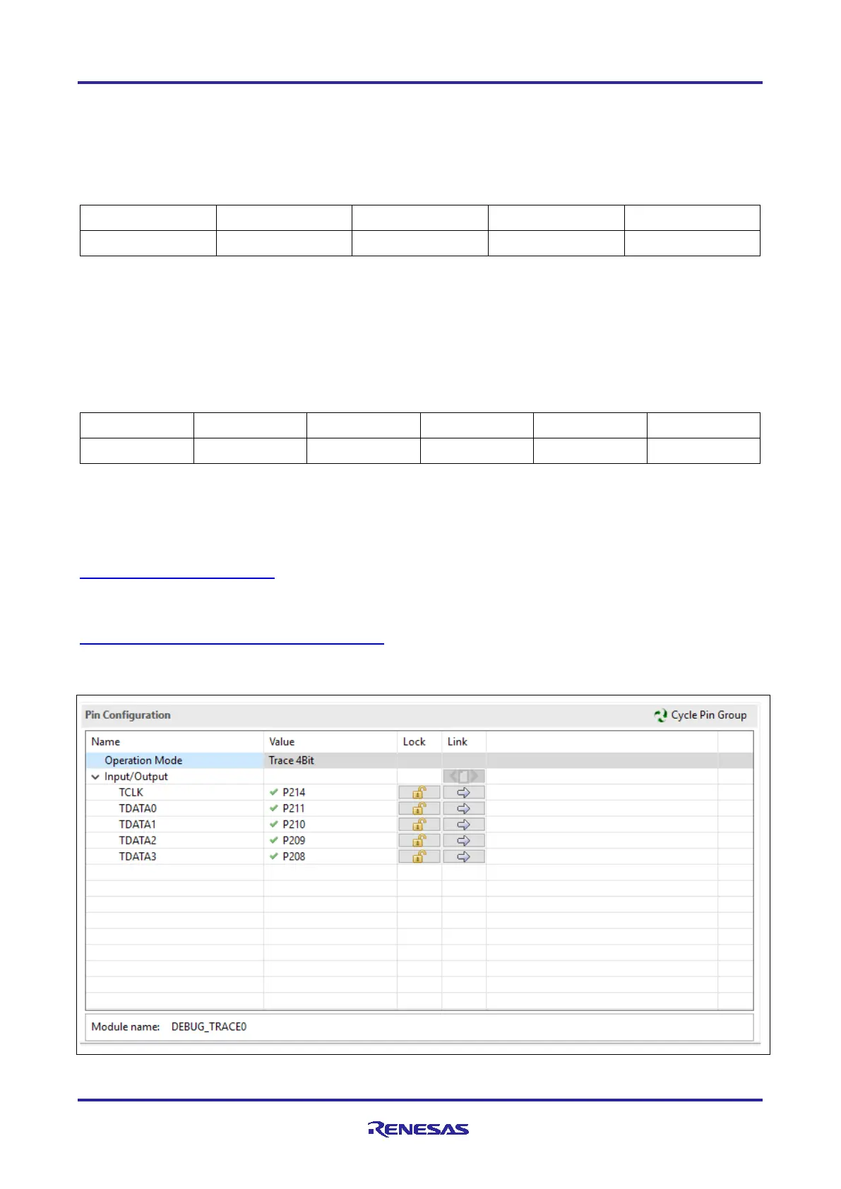
Trace ports can also be enabled at runtime by using the Pin Configurator in Renesas FSP, but some trace
data may be lost in this case.
Figure 6. Enabling Trace Ports at Runtime Using FSP Configurator

 Loading...


