Renesas RA Family RA4 Quick Design Guide
R01AN5988EU0100 Rev.1.00 Page 22 of 51
Jul.21.21
There are thirteen or fourteen types of resets for Arm
®
Cortex-M33 devices, depending on the specific
device.
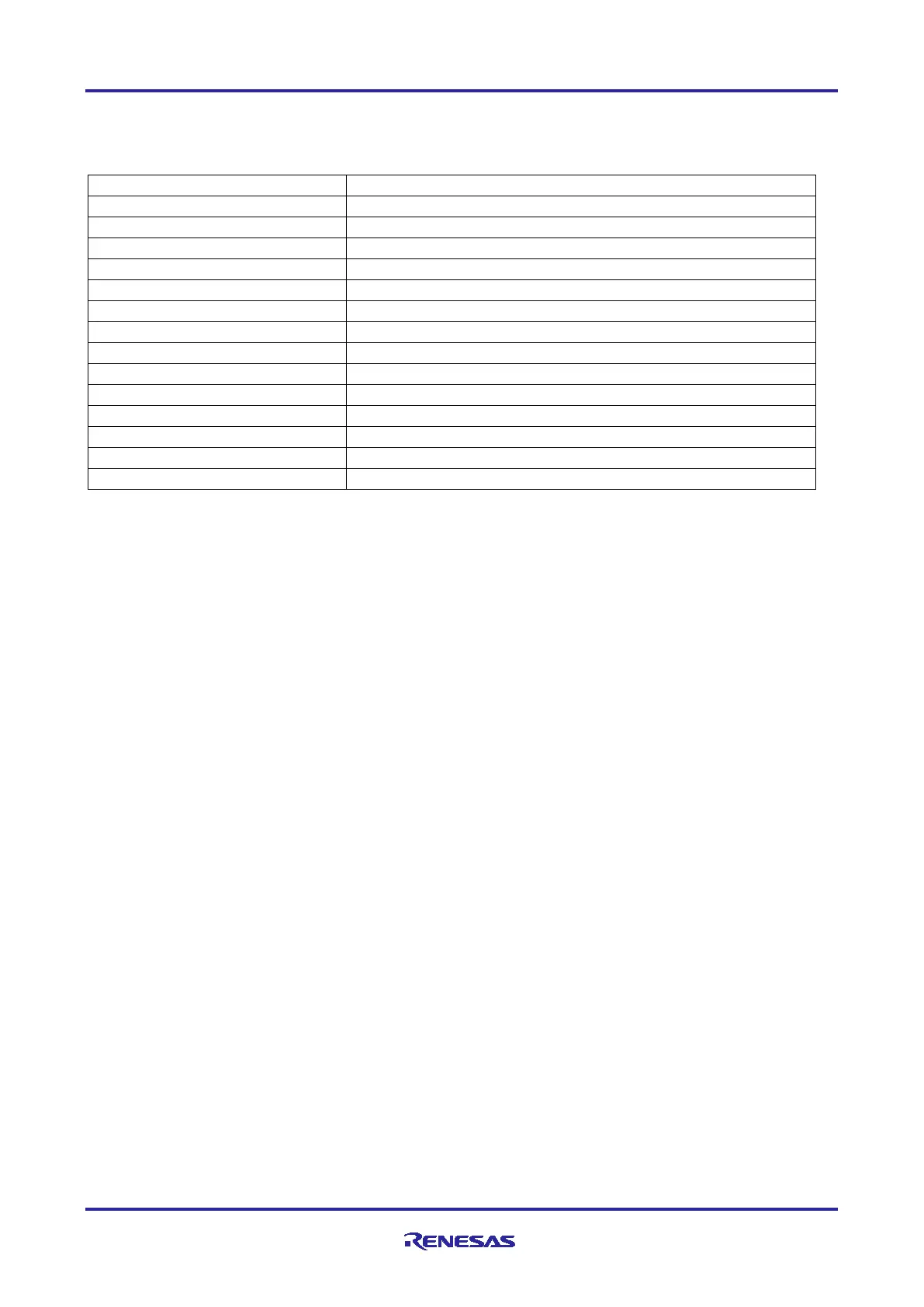
Table 12. Arm
®
Cortex-M33 Device Resets
VCC rises (voltage detection: VPOR)
Independent watchdog timer reset
The independent watchdog timer underflows, or a refresh occurs
The watchdog timer underflows, or a refresh occurs
VCC falls (voltage detection Vdet0)
VCC falls (voltage detection Vdet1)
VCC falls (voltage detection Vdet2)
SRAM parity error detection
Bus master MPU error reset
Bus Master MPU error detection
TrustZone error detection
Cache Parity error reset
*1
Cache Parity error detection
Deep software standby reset
Deep software standby mode is canceled by an interrupt
Note 1. RA4M3 devices only.
6.1 Pin Reset
When the RES# pin is driven low, all processing is aborted and the MCU enters a reset state. To reset the
MCU while it is running, RES# should be held low for the specified reset pulse width. Refer to the “Reset
Timing” section of the “Electrical Characteristics” chapter of the Hardware User’s Manual for more detailed
timing requirements. Also refer to section 2 of this document, “Emulator Support” for details on reset circuitry
in relation to debug support.
There is no need to use an external capacitor on the RES# line because the POR circuit holds it low
internally for a good reset and a minimum reset pulse is required to initiate this process.
6.2 Power-On Reset
There are two conditions that will generate a power-on reset (POR):
1. If the RES# pin is in a high-level state when power is supplied.
2. If the RES# pin is in a high-level state when VCC is below V
POR.
After VCC has exceeded the power-on reset voltage (V
POR
) and the power-on reset time (t
POR
) has elapsed,
the chip is released from the power-on reset state. The power-on reset time is a period that allows for
stabilization of the external power supply and the MCU. Refer to the “POR and LVD Characteristics” section
of the “Electrical Characteristics” chapter of the Hardware User’s Manual for voltage level and timing details.
Because the POR circuit relies on having RES# high concurrently with VCC, don’t place a capacitor on the
reset pin. This will slow the rise time of RES# in relation to VCC, preventing the POR circuit from properly
recognizing the power-on condition.
If the RES# pin is high when the power supply (VCC) falls to or below V
POR
, a power-on reset is generated.
The chip is released from the power-on state after VCC has risen above V
POR
and the t
POR
has elapsed.
After a power-on reset, the PORF bit in RSTSR0 is set to 1. Following a pin reset PORF is cleared to 0.
6.3 VBATT-Selected Voltage Power-On Reset
When the voltage at the VCC pin drops, power can be supplied to the RTC, LOCO and sub-clock oscillator
from the VBATT pin. When a power supply drop from the VCC pin is detected, connection to power is
switched from the VCC pin to the VBATT pin.
For Arm Cortex-M4 devices, when this occurs a reset can be generated to flag the switch from VCC to
VBATT. Details of this reset and the related VBATT configuration can be found in the Battery Backup
Function chapter of the MCU Hardware User’s Manual.

 Loading...


