Renesas RA Family RA4 Quick Design Guide
R01AN5988EU0100 Rev.1.00 Page 12 of 51
Jul.21.21
3. MCU Operating Modes
The RA4 MCU series can enter one of two modes after reset: Single-chip mode or SCI/USB boot mode. The
boot mode is selected by the MD pin:
Table 6. Operating Modes Available at Reset
Single-chip mode
SCI/USB boot mode
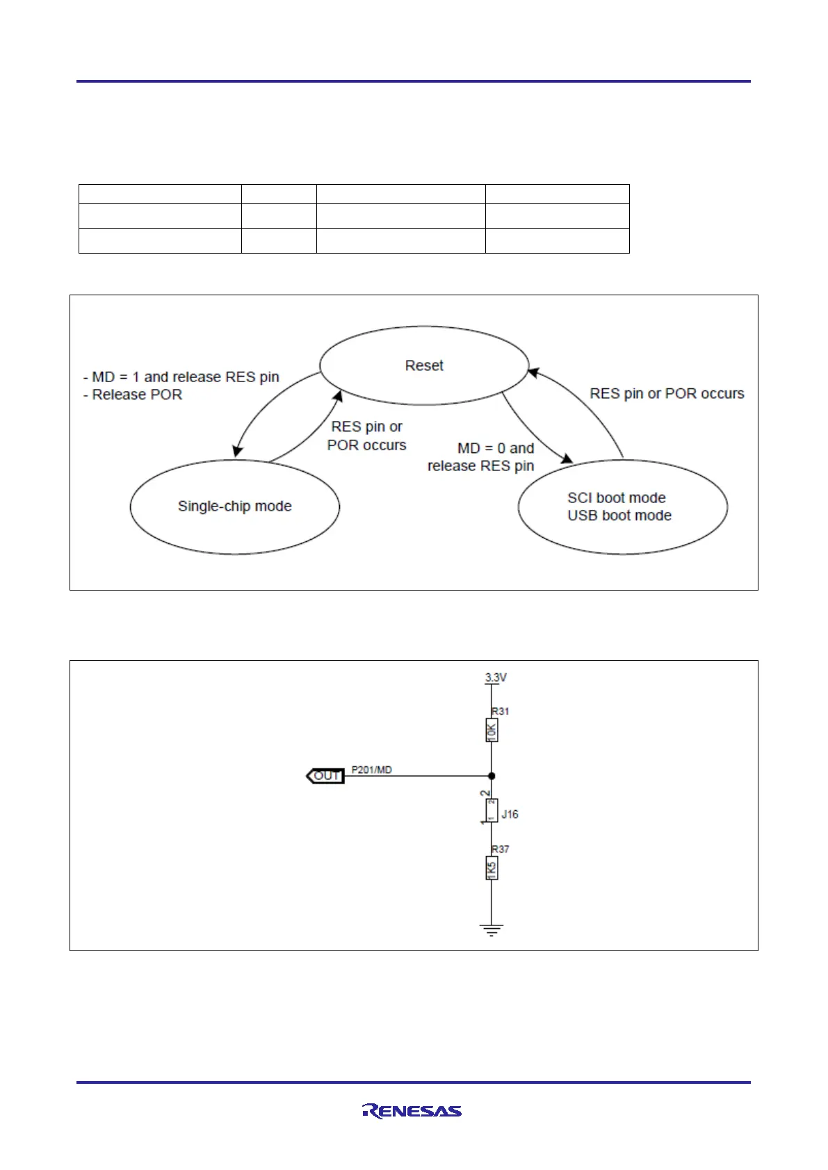
Figure 7 shows operating mode transitions as determined by the Mode-Setting (MD) pin.
Figure 7. Mode Setting Pin level and Operating Mode
A typical MCU boot mode circuit includes a jumper and a couple of resistors to allow selections to connect
the MD pin to VCC or Ground.
Figure 8. Typical Circuit for MCU Boot Mode Selection
4. Option Setting Memory
The option-setting memory determines the state of the MCU after a reset. It is allocated to the configuration
setting area and the program flash area of the flash memory. Option setting memory may be different in size
and layout for Arm Cortex-M33 based devices.

 Loading...


