4.Service Tables
54
Bit Switches
1
• Do not adjust a bit switch or use a setting that is described as "Not used", as this may cause the machine
to malfunction or to operate in a manner that is not accepted by local regulations. Such bits are for use
only in other areas, such as Japan.
Default settings for bit switches are not listed in this manual. Refer to the System Parameter List printed by the
machine.
System Switches
System Switch 00 (SP No. 1-101-001)
No Function Comments
0 Dedicated transmission
parameter programming
0: Disabled
1: Enabled
Set this bit to 1 before changing any dedicated transmission parameters.
This setting is automatically reset to "0" after turning off and on.
1 Not used Do not change this setting.
2 Technical data printout on
the Journal
0: Disabled
1: Enabled
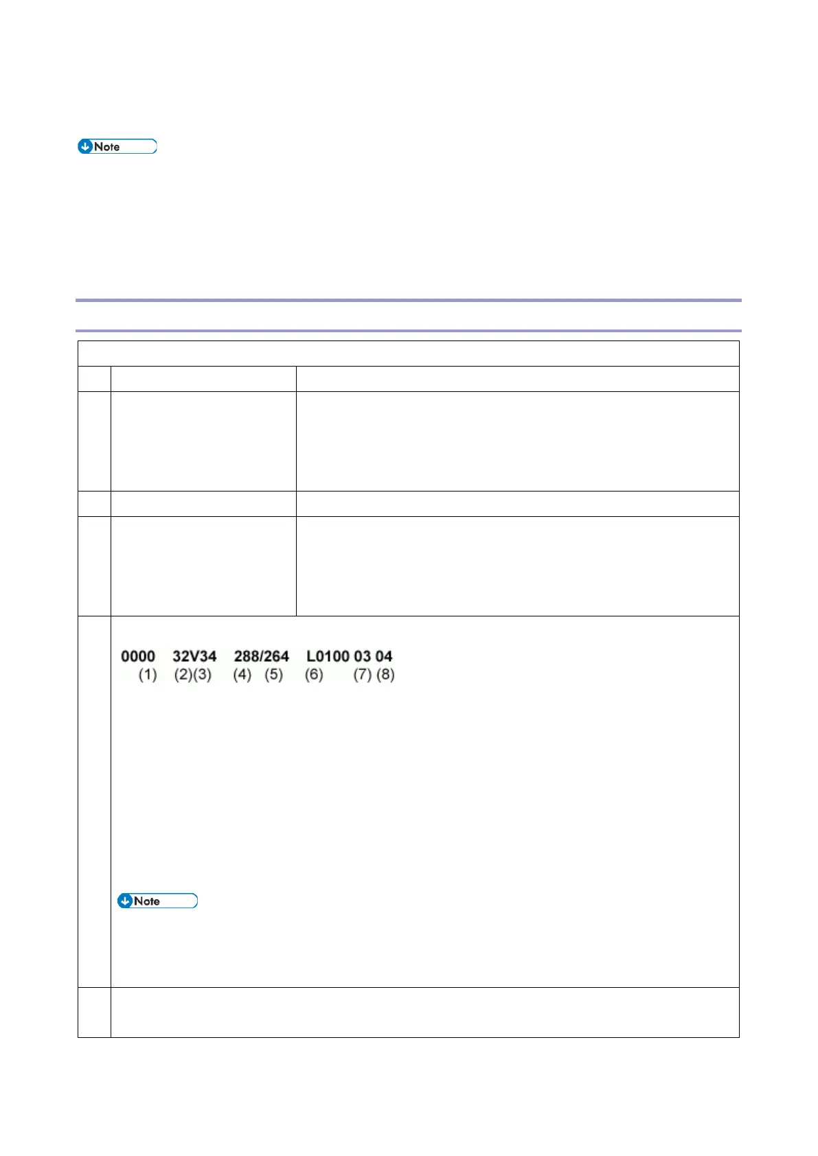
1: Instead of the personal name, the following data are listed on the
Journal for each G3 communication.
Example:
(1): EQM value (Line quality data). A larger number means more errors.
(2): Symbol rate (V.34 only)
(3): Final modem type used
(4): Starting data rate (for example, 288 means 28.8 kbps)
(5): Final data rate
(6): Rx revel (see below for how to read the rx level)
(7): Total number of error lines that occurred during non-ECM reception.
(8): Total number of burst error lines that occurred during non-ECM reception.
• EQM and rx level are fixed at "FFFF" in tx mode.
• The seventh and eighth numbers are fixed at "00" for transmission records and ECM reception
records.
Rx level calculation
Example:
 Loading...