Home
Rigol
Test Equipment
DHO800 Series
Rigol DHO800 Series User Manual
4
of 1
of 1 rating
253 pages
Give review
Manual
Specs
To Next Page
To Next Page
To Previous Page
To Previous Page
Loading...
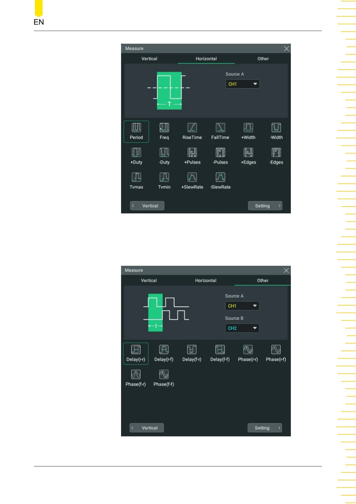
Figure 10.5 Horizontal Measurement Items
•
Other
:
Delay (r
-r), Delay (r
-f
), Delay (f
-r), Delay (f
-f
), Phase (r
-r), Phase (r
-f
),
Phase(f
-r), and Phase (f
-f
).
Figure 10.6 Other Measurement Items
Measurements
Copyright ©RIGOL TECHNOL
OGIES CO
., L
TD
. All rights reser
ved.
DHO800 User Guide
135
148
150
Table of Contents
Table of Contents
3
Safety Requirement
15
General Safety Summary
15
Safety Notices and Symbols
16
Measurement Category
17
Ventilation Requirement
18
Working Environment
18
Care and Cleaning
20
Environmental Considerations
20
Product Features
21
Document Overview
22
Quick Start
24
General Inspection
24
Appearance and Dimensions
24
Figure 4.1 Front View
24
To Prepare for Use
25
To Adjust the Supporting Legs
25
Figure 4.2 Side View
25
Figure 4.3 Adjusting the Supporting Legs
25
To Connect to Power
26
Turn-On Checkout
26
Figure 4.4 to Connect to Power
26
Table 4.1 Power Adaptor Specifications
26
To Set the System Language
27
To Connect the Probe
27
Function Inspection
28
Figure 4.5 Connecting the Passive Probe
28
Probe Compensation
29
Figure 4.6 Using the Compensation Signal
29
Figure 4.7 Square Waveform Signal
29
Product Overview
30
Figure 4.8 Probe Compensation
30
Front Panel Overview
31
Figure 4.9 Front Panel (2-Channel Model)
31
Figure 4.10 Front Panel (4-Channel Model)
31
Rear Panel Overview
37
Figure 4.11 Rear Panel
37
User Interface Overview
38
Figure 4.12 User Interface
38
Touch Screen Gestures
40
Tap
41
Drag
41
Figure 4.13 Tap Gesture
41
Pinch&Stretch
42
Figure 4.14 Drag Gesture
42
Figure 4.15 Pinch&Stretch Gesture
42
Parameter Setting Method
43
Figure 4.16 English Input Interface
43
Figure 4.17 Chinese Input Interface
45
Figure 4.18 String Keypad
46
Figure 4.19 Numeric Keypad
47
To Use the Security Lock
48
Figure 4.20 to Use the Security Lock
48
To Use the Built-In Help System
49
Vertical System
50
To Enable or Disable the Analog Channel
50
Figure 5.1 Vertical Menu
50
To Adjust the Vertical Scale
51
To Adjust the Vertical Offset
53
To Specify Channel Coupling
54
To Specify Bandwidth Limit
54
To Specify Input Impedance
55
To Invert a Waveform
55
To Set Probe
56
Figure 5.2 Waveform Invert On/Off
56
Figure 5.3 Probe Setting Menu
56
Table 5.1 Probe Ratio
57
To Specify the Amplitude Unit
58
To Adjust Bias
58
To Specify the Skew
59
To Turn the Channel Label Display On/Off
59
Figure 5.4 Zero Offset
59
Horizontal System
61
To Adjust the Horizontal Time Base
61
Figure 6.1 Horizontal Menu
61
To Adjust the Horizontal Position
62
Zoom Mode (Delayed Sweep)
63
Figure 6.2 Zoom Mode
64
Acquisition System
65
Acquisition Mode
65
Figure 7.1 Horizontal Menu
65
Sampling Mode
67
Figure 7.2 Display Modes
67
Sample Rate
68
Memory Depth
69
Figure 7.3 Memory Depth
69
Horizontal Expansion Reference
70
Roll Mode
71
XY Mode
71
Figure 7.4 XY Menu
72
Figure 7.5 Measurement Schematic Diagram of Phase Deviation
73
Triggering the Oscilloscope
75
Trigger Source
75
Trigger Level
76
Trigger Mode
76
Figure 8.1 Schematic Diagram of the Acquisition Memory
77
Trigger Coupling
78
Trigger Holdoff
78
Noise Rejection
79
Trigger Type
79
Figure 8.2 Trigger Holdoff
79
Edge Trigger
80
Figure 8.3 Edge Trigger Setting Menu
80
Pulse Width Trigger
81
Figure 8.4 Positive/Negative Pulse Width
82
Figure 8.5 Pulse Width Trigger Setting Menu
82
Slope Trigger
84
Figure 8.6 Positive Slope Time/Negative Slope Time
84
Figure 8.7 Slope Trigger Setting Menu
85
Video Trigger
87
Figure 8.8 Video Trigger Setting Menu
87
Table 8.1 Video Standard
88
Pattern Trigger
89
Figure 8.9 Pattern Trigger
90
Figure 8.10 Pattern Trigger Setting Menu
90
Duration Trigger
92
Figure 8.11 Duration Trigger
92
Figure 8.12 Duration Trigger Setting Menu
93
Timeout Trigger
95
Figure 8.13 Timeout Trigger
95
Figure 8.14 Timeout Trigger Menu
95
Runt Trigger
97
Figure 8.15 Runt Trigger
97
Figure 8.16 Runt Trigger Setting Menu
97
Window Trigger
99
Figure 8.17 Window Trigger Setting Menu
99
Delay Trigger
101
Figure 8.18 Delay Trigger
101
Figure 8.19 Delay Trigger Setting Menu
102
Setup/Hold Trigger
104
Figure 8.20 Setup/Hold Trigger
104
Figure 8.21 Setup/Hold Trigger Setting Menu
105
Nth Edge Trigger
106
Figure 8.22 Nth Edge Trigger
107
Figure 8.23 Nth Edge Trigger Setting Menu
107
RS232 Trigger
109
Figure 8.24 Schematic Diagram of RS232 Protocol
109
Figure 8.25 RS232 Trigger Setting Menu
109
I2C Trigger
111
Figure 8.26 Sequence Diagram of I2C Protocol
112
Figure 8.27 I2C Trigger Setting Menu
112
Figure 8.28 Binary Format Setting
114
Figure 8.29 Hexadecimal Format Setting
114
SPI Trigger
115
Figure 8.30 Sequential Chart of SPI Bus
115
Figure 8.31 SPI Trigger Setting Menu
116
Trigger Output Connector
118
Math Operation
119
Figure 9.1 Math Menu
119
Arithmetic Operation
120
Figure 9.2 Waveform Display Window of the Operation Results
120
Figure 9.3 Arithmetic Operation Menu
121
Figure 9.4 Operation Result Display Window
121
Function Operation
123
Figure 9.5 Function Operation Menu
124
Figure 9.6 Operation Result Display Window
125
FFT Operation
127
Figure 9.7 FFT Operation Menu
128
Figure 9.8 FFT Operation Window
128
Table 9.1 Window Function
130
Figure 9.9 Peak Search
131
Logic Operation
132
Figure 9.10 Logic Operation Menu
132
Table 9.2 Logic Operation
133
Figure 9.11 Operation Result Display Window
134
Digital Filter
135
Figure 9.12 Digital Filter Menu
136
Figure 9.13 Operation Result Display Window
137
Measurements
140
Auto Scale
140
Auto Measurements
141
Measurement Parameter
141
Time Parameters
141
Figure 10.1 Time Parameters
141
Count Values
142
Delay and Phase Parameters
144
Figure 10.2 Delay and Phase Parameters
144
Voltage Parameters
146
Figure 10.3 Voltage Parameters
146
Other Parameters
147
Select the Measurement Item
148
Figure 10.4 Vertical Measurement Items
148
Figure 10.5 Horizontal Measurement Items
149
Figure 10.6 Other Measurement Items
149
Measurement Settings
150
Figure 10.7 Measurement Settings Menu
150
Remove the Measurement Results
153
Cursor Measurements
154
Figure 10.8 Cursors
154
Manual Mode
156
Figure 10.9 Manual Mode Setting Menu
156
Track Mode
158
Figure 10.10 Manual Cursor Measurement Example
158
Figure 10.11 Track Mode Setting Menu
159
Figure 10.12 Track Measurement (before Horizontal Expansion)
160
XY Mode
161
Figure 10.13 Track Measurement (after Horizontal Expansion)
161
Figure 10.14 XY Mode Setting Menu
161
Digital Voltmeter (DVM) and Frequency Counter
163
Digital Voltmeter (DVM)
163
Measurement Settings
163
Figure 11.1 DVM Setting Menu
164
Remove the Measurement
165
Frequency Counter
165
Measurement Settings
166
Figure 11.2 Frequency Counter Setting Menu
166
Reset Statistics
167
Remove the Measurement
167
Histogram Analysis
168
To Enable or Disable the Histogram Function
168
Figure 12.1 Histogram Menu
168
To Select the Histogram Type
169
To Select the Histogram Source
169
To Set the Histogram Height
169
Figure 12.2 Histogram Analysis Interface
169
To Set the Histogram Range
170
Histogram Analysis Results
170
Figure 12.3 Histogram Analysis Results
171
To Remove Results
172
To Clear Statistics
172
Reference Waveform
173
To Enable Ref Function
173
To Set the Reference Waveform
173
Figure 13.1 Reference Waveform Menu
173
To Set the Ref Waveform Display
174
Export and Import Operation
175
Pass/Fail Test
177
Figure 14.1 Passfail Menu
177
Figure 14.2 Passfail Menu-Simplified
177
To Enable or Disable the Pass/Fail Test Function
178
To Select the Source
178
To Create a Mask
178
To Set the Output Form of the Test Results
179
To Start or Stop the Pass/Fail Test Operation
180
To Display the Statistics of the Test Results
180
Figure 14.3 Pass/Fail Test Interface
180
Protocol Decoding
182
Parallel Decoding
182
Figure 15.1 Schematic Diagram of Parallel Decoding
182
Clock Setting (CLK)
183
Figure 15.2 Parallel Decoding Menu
183
Bus Setting
184
Table 15.1 Bus Setting
184
Display-Related Settings
185
Event Table
185
RS232 Decoding
186
Figure 15.3 Parallel Decoding Event Table
186
Figure 15.4 Schematic Diagram of RS232 Serial Bus
187
Figure 15.5 RS232 Decoding Menu
187
Source Setting
188
To Set Data Package
189
Display-Related Settings
189
Event Table
190
Figure 15.6 RS232 Decoding Event Table
190
I2C Decoding
191
Figure 15.7 I2C Serial Bus
191
Figure 15.8 I2C Decoding Menu
191
Source Setting
192
Display-Related Settings
192
Event Table
193
Figure 15.9 I2C Decoding Event Table
193
SPI Decoding
194
Figure 15.10 SPI Serial Bus
194
To Set the Source
195
Figure 15.11 SPI Decoding Menu
195
To Set Mode and Data
196
Display-Related Settings
197
Event Table
197
Figure 15.12 SPI Decoding Event Table
198
Multi-Pane Windowing
199
Figure 16.1 "Add Window" Menu
199
Waveform Recording and Playing
201
Common Settings
201
Figure 17.1 "Record" Menu
201
Record Options
202
Play Options
203
Figure 17.2 Minimized "Play" Menu
204
Search and Navigation
206
Search
206
Figure 18.1 Search Menu
206
Navigation
208
Figure 18.2 Marktable Display
208
Figure 18.3 Navigation Menu
209
Figure 18.4 Simplified Navigation Menu
209
Figure 18.5 "Search Event" Navigation Setting Menu
210
Figure 18.6 "Frame Segment" Navigation Setting Menu
210
Display Control
212
Display Type
212
Persistence Time
212
Figure 19.1 Display Setting Menu
212
Waveform Intensity
213
To Set the Screen Grid
213
Display Settings
213
Show Scale
214
Color Grade
214
Waveform Freeze
214
Store and Load
215
To Enter the Storage Menu
215
To Save a File
215
To Save Image
215
Figure 20.1 Image Saving Setting Menu
216
To Save Wave
217
Figure 20.2 Waveform Saving Setting Menu
218
Save Setup
219
Figure 20.3 Setup Saving Setting Menu
219
Binary Data Format (.Bin)
220
Table 20.1 bin File Format
220
Table 20.2 File Header
221
Table 20.3 Waveform Header
221
To Load a File
223
Table 20.4 Waveform Data Header
223
Firmware Upgrade
224
Figure 20.4 Load Setting Menu
224
Disk Management
225
Figure 20.5 Upgrade Menu
225
Figure 20.6 Disk Management Interface
226
System Utility Function Setting
228
I/O Setting
228
Basic Settings
230
About this Oscilloscope
232
Other Settings
233
Auto Config
233
Selfcal
234
Option List
234
Quick Action Settings
234
Figure 21.1 Self-Calibration Menu
234
Figure 21.2 Quick Menu
235
Self-Check
237
Remote Control
238
Remote Control Via USB
239
Remote Control Via LAN
239
Troubleshooting
241
Appendix
242
Appendix A: Options and Accessories
242
Appendix B: Warranty
242
Appendix C: Factory Settings
243
Table 24.2 Factory Settings
248
Other manuals for Rigol DHO800 Series
Quick Guide
29 pages
4
Based on 1 rating
Ask a question
Give review
Questions and Answers:
Need help?
Do you have a question about the Rigol DHO800 Series and is the answer not in the manual?
Ask a question
Rigol DHO800 Series Specifications
General
Brand
Rigol
Model
DHO800 Series
Category
Test Equipment
Language
English
Related product manuals
Rigol DHO802
253 pages
Rigol DHO804
253 pages
Rigol DHO814
253 pages
Rigol DHO900
253 pages
Rigol DHO924
288 pages
Rigol DHO914
288 pages
Rigol DHO924S
288 pages
Rigol DHO1204
261 pages
Rigol DHO914S
288 pages
Rigol DHO1202
261 pages
Rigol DHO900 Series
289 pages
Rigol DHO1000 Series
261 pages
 Loading...