82 Publication IASIMP-QS003B-EN-P - October 2009
Chapter 6 Prepare the Kinetix 6000 Multi-axis Servo Drive System
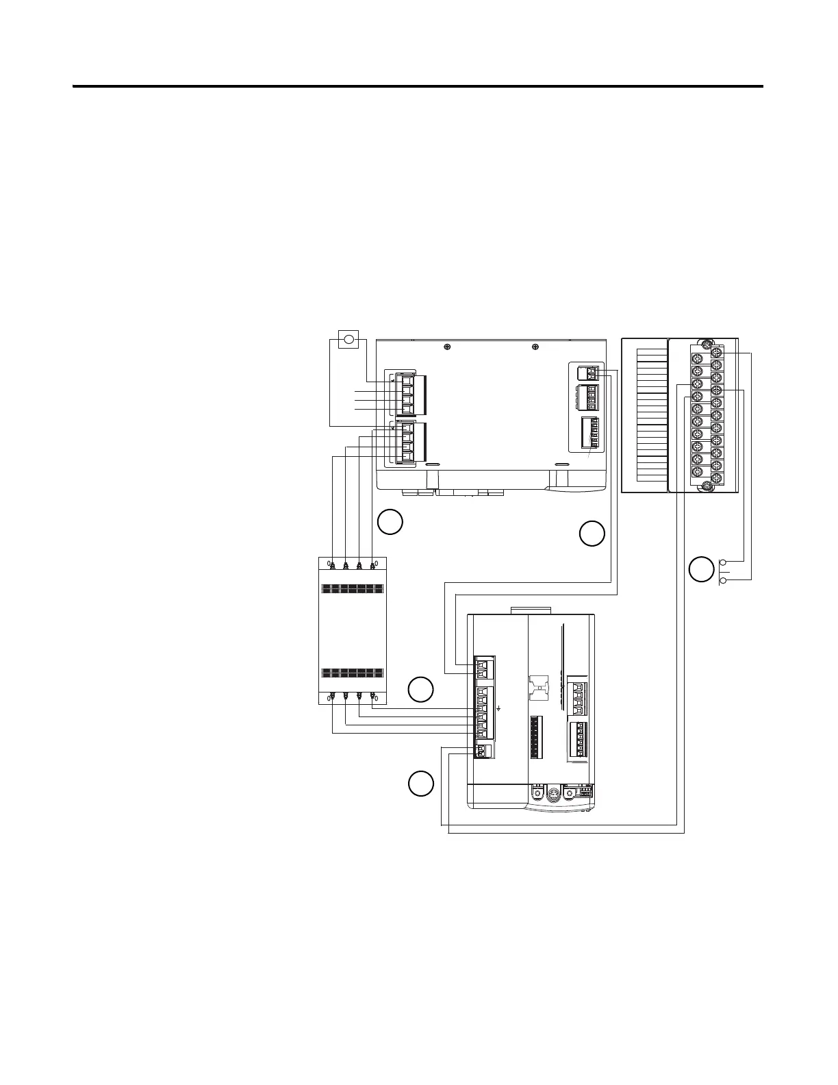
Wire Power to the Integrated Axis Module
This procedure shows power connections to the integrated axis module (IAM) when using
the line interface module (LIM). The AC conductor sizes are based on the motor load
requirements.
2094-AC09-M02
1. Wire the LIM module
load terminals to the AC
line filter, line terminals.
2. Wire the AC line filter
load terminals to the IAM
line terminals.
3. Wire the 230V control
power from the LIM to
the IAM module.
4. Wire the E1 safety coil on
the LIM module to the
E-stop button.
5. Wire the E2 safety coil on
LIM module to the
CONT EN contacts on
the IAM module.
195-265 VAC LINE, 50/60 Hz
L3
L2
L1
230 VAC SUPPLY
CTRL2
CTRL1
195-265 VAC LOAD, 50/60 Hz
L3'
L2'
L1'
CONTROL VAC
AUX2
AUX2
AUX1
AUX1
I/O_COM
I/O_PWR
I/O_COM
I/O_PWR
I/O_COM
I/O_PWR
24 VDC SUPPLY
1 2
1 2 3 4
1 2 3 4
1 2 3 4
1 2 3 4 5 6
IO_PWR1
IO_COM1
IO_PWR1
IO_COM1
IO_PWR1
IO_COM1
COIL_E1
COIL_E2
ALRM_M
SHIELD
ALRM_B
ALRM_COM
CONSTAT_11
CONSTAT_12
CONSTAT_21
CONSTAT_22
CONSTAT_31
CONSTAT_32
CONSTAT_53
CONSTAT_54
SHIELD
1
3
5
7
9
11
13
15
17
19
21
2
4
6
8
10
12
14
16
18
20
IOL
BAUD
RATE
TX
RX
DPI
DC-
DC+
L3
L2
L1
CONT EN-
CONT EN+
W
V
U
MBRK -
MBRK +
COM
PWR
DBRK -
DBRK +
CTRL 2
CTRL 1
1 2 3 4
1 2 3 4 5 6
1 2
1 2 3 4 5 6
1 2
1 2 3 4 5 6 7 8 9
L1
L2
L3
L1 L2 L3 E
L1 L2 L3 E
CL2
CL1
1
7
6
8
LINE
LOAD
Line Interface Module
AC RFI
Line
Filter
E-Stop
Top View
Integrated Axis Module
Front View
Top View
5
1
2
5
4
3
Incoming Power

 Loading...


