13
FA ROTEX GW - 09/2012
4 x Installation
4.4.2 Wall mounting
Precondition
– The installation site and mounting surface complies with the
respective country-specific regulations, as well as the mini-
mum requirements described in chapter 4.4.1.
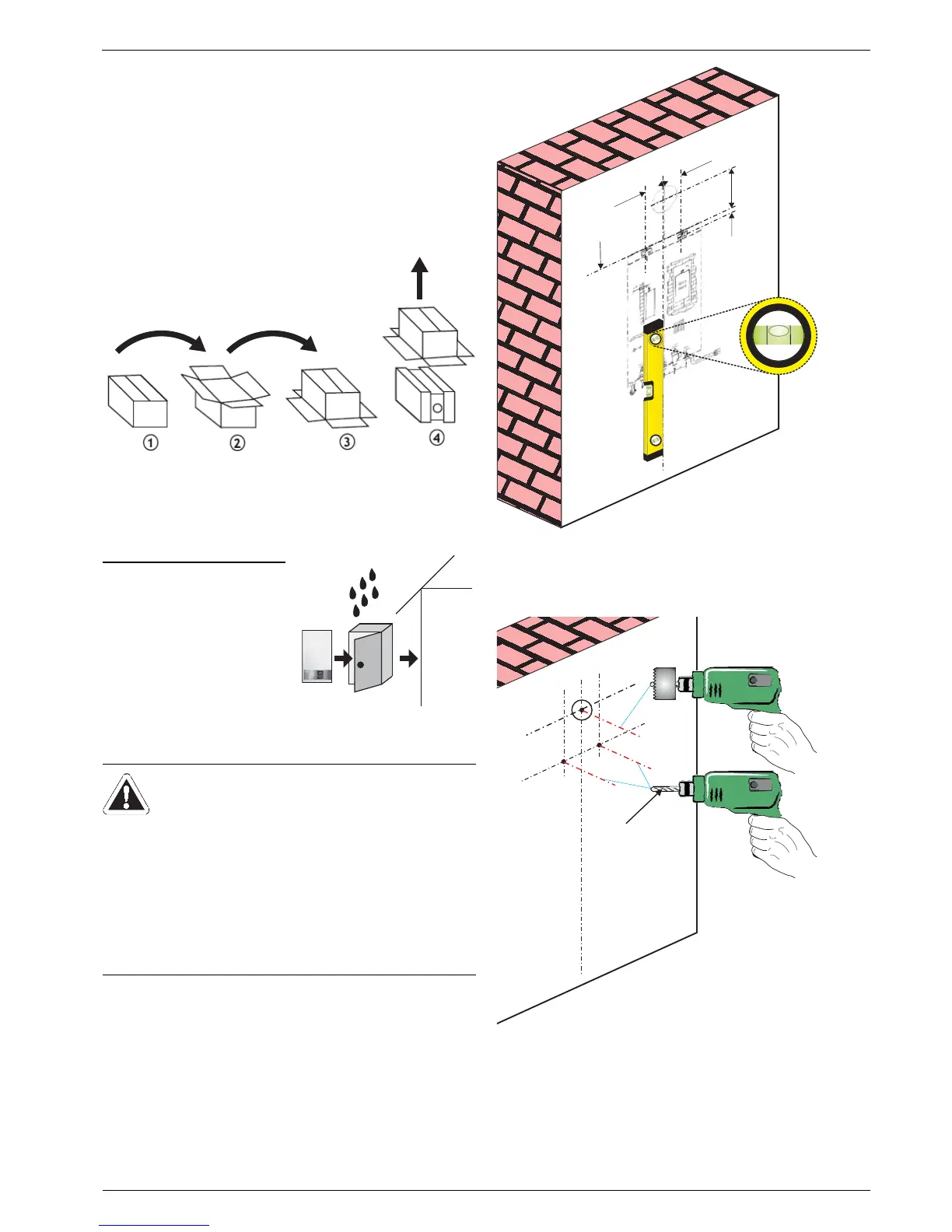
Installation
Ɣ Remove the packaging
Ɣ Check the delivery for completeness and damage. Any
defects should be advised to the supplier.
Ɣ and dispose of it in an environmentally sound manner.
If the unit is to be installed outdoors, in addition to the require-
ments for the site of installation, the ROTEX GW must be
mounted in a protective cabinet.
Ɣ With room air dependent or limited room air independent
operation, the top of the cabinet must be provided with an
adequately sized cut-out for ventilation to the outside (see
chapter 4.2.2 and 4.2.3).
Ɣ Mount the template on the wall under consideration of the
constructional conditions and the minimum distances (see
chapter 4.1).
Ɣ Drill the holes Ø 10 mm for the fixing hooks for the ROTEX
GW as per the mounting template.
Fig. 4-4 Remove the packaging
Only for installation in a cabinet:
Ɣ Mount the cabinet on the
external wall.
Follow the mounting tem-
plate and the minimum dis-
tances of the ROTEX GW
when selecting the protective
cabinet (see chapter 4.1).
Fig. 4-5 Mounting the protec-
tive cabinet
WARNING!
Heating units intended for wall mounting must only be
mounted on non-flammable heat-resistant surfaces
with adequate carrying capacity (e.g. brickwork, not
the back wall of the cabinet).
Danger of gas and water escape and associated
explosion and flooding risk in the event of unsuitable
mounting location.
Ɣ Remove / cut out the cabinet back wall and mount
the heating unit directly on the solid wall with
adequate carrying capacity.
A Drilled holes for wall hooks (Ø 10 mm)
B Wall breakthrough (Ø 135 mm when using GW1 kit)
Fig. 4-6 Placing the mounting template
A Drilled holes for wall hooks (Ø 10 mm)
B Wall breakthrough (Ø 135 mm when using GW1 kit)
Fig. 4-7 Creating the drilled holes
 Loading...


