15
FA ROTEX GW - 09/2012
4 x Installation
Permissible height of the flue gas system
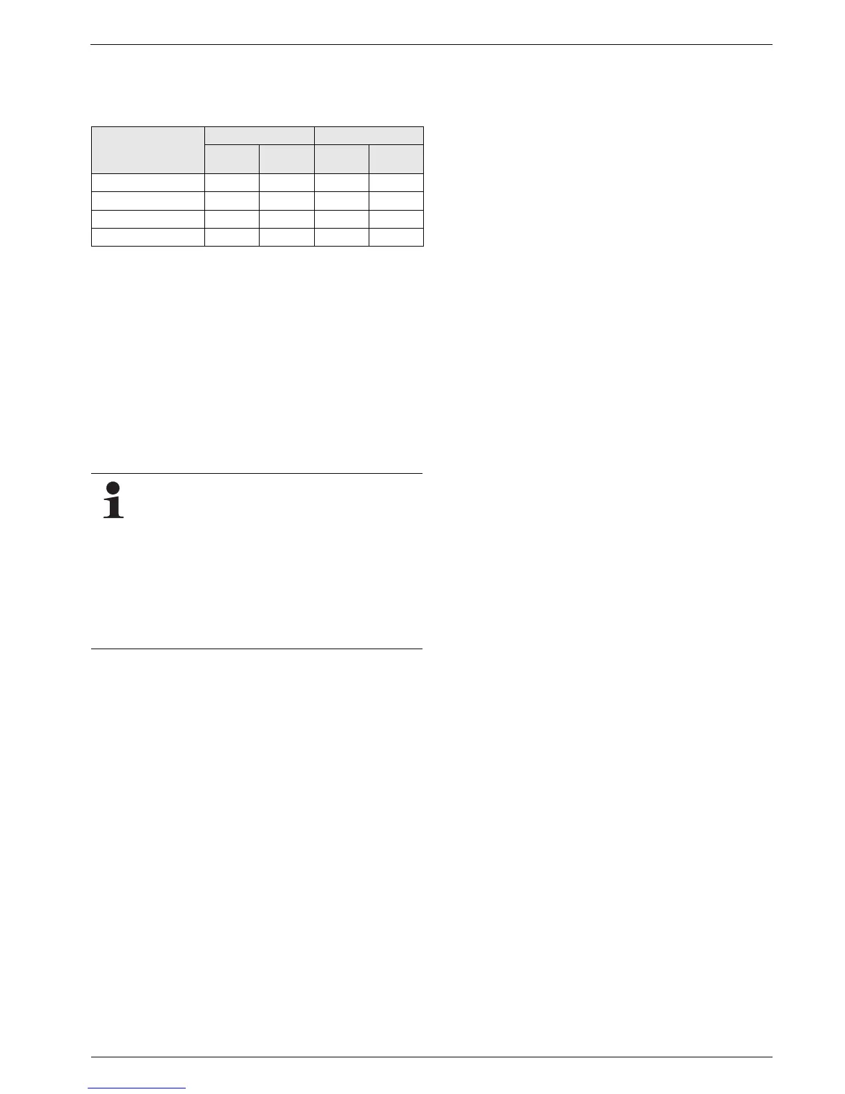
Tab. 4-2 shows the maximum permissible height of the flue gas
line for the case that the ROTEX GW is operated in the nominal
output range.
Tab. 4-2 Maximum height for the flue gas duct in m
4.5.2 Connect flue gas line to the ROTEX GW
Requirements
– The flue system fulfils the requirements described in
chapter 4.5.1.
– The flue system fulfils any other required national or regional
safety requirements.
– The ROTEX GW is correctly mounted on the wall.
Connection
Ɣ Connect the ROTEX GW to the flue gas system within the
place of installation (for connection dimensions, see fig. 4-1).
Ɣ Place the nameplate of the flue gas pipe in the installation
room.
Installation version
(according to
fig. 4-3)
GW 22C GW 26C
DN 60 DN 80 DN 60 DN 80
15
1)
10
3)
5
1)
10
3)
26
2)
12
4)
6
2)
12
4)
36
2)
12
4)
6
2)
12
4)
45
2)
10
4)
5
2)
10
4)
1) Shaft cross section for DN 60: 115 mm x 115 mm
2) Concentric flue gas/supply line: DN 60/100
3) Shaft cross section for DN 80: 135 mm x 135 mm
4) Concentric flue gas/supply line: DN 80/125
Basically, any flue gas line that complies with the
minimum requirements according to the EN 14471 and
that has the CE-labelling can be connected (see
chapter 4.5.1).
Each flue gas line must be installed with a suitable test
adapter for checking and setting the combustion
values. A test adapter (DN 60/100) is included in the
delivery of the ROTEX GW.
We recommend to use the associated ROTEX LAS-
sets (see fig. 4-11). They satisfy all requirements and
are also fitted with special acid-proof seals.
 Loading...


