22
FA ROTEX GW - 09/2012
5 x Start-up
5 Start-up
Incorrect start-up makes the manufacturer's guarantee for the
unit void. If you have questions, please contact our Technical
Customer Service.
5.1 Initial start-up
Once the ROTEX GW is installed and fully connected, it can be
put into operation by expert technicians.
5.1.1 Requirements
– The ROTEX GW is fully connected.
– Optional accessories have been mounted and connected up.
– The control valves of the heating system are open.
– The gas supply to the ROTEX GW is open.
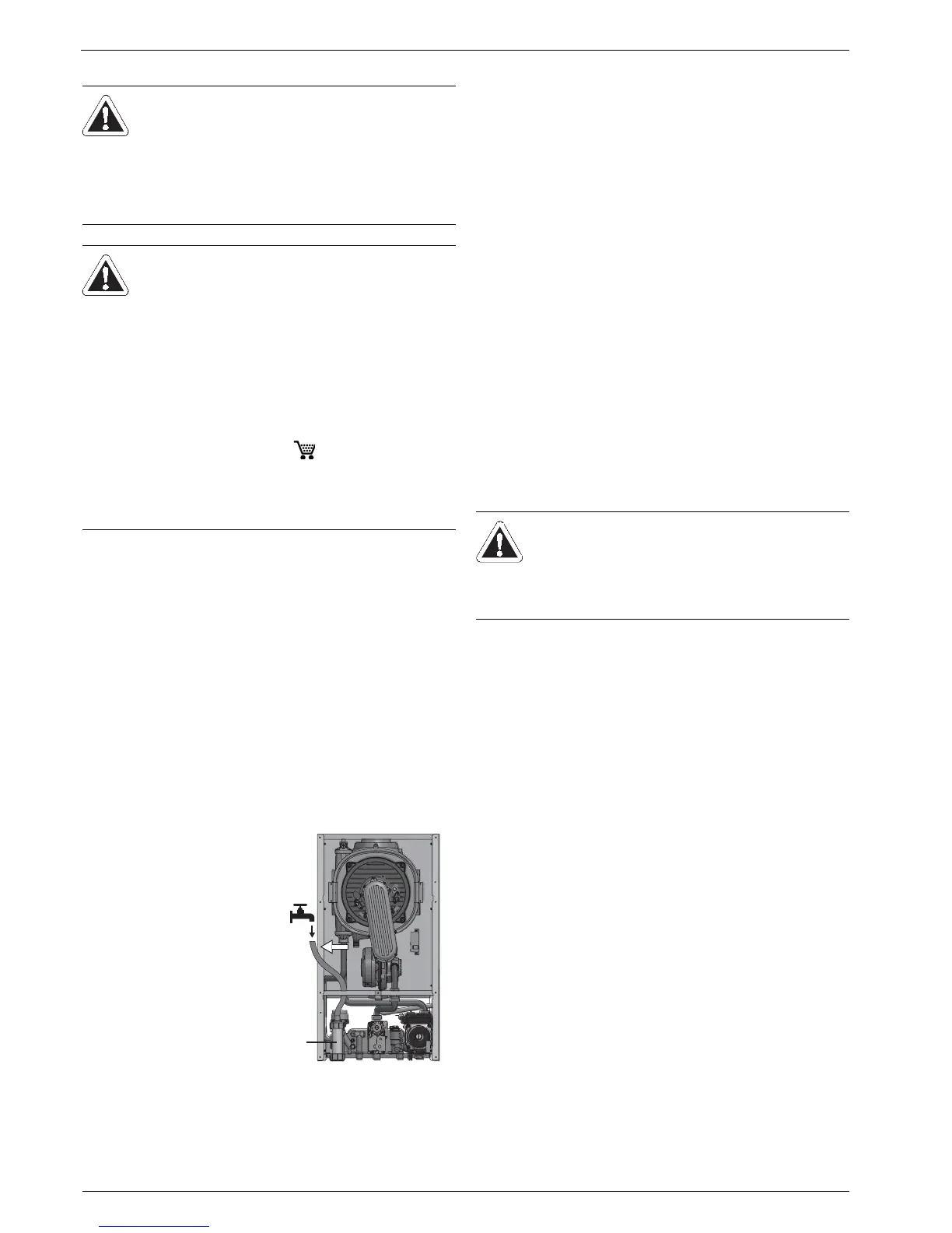
5.1.2 Filling the condensate siphon
5.1.3 Checks before initial start-up
Ɣ Check all connections for leakage.
Ɣ Check all the points on the checklist (see chapter 5.1.7). Log
the test results on the checklist.
Ɣ Only if all points on the checklist can be answered with Yes
may the ROTEX GW be started up.
5.1.4 Filling the system and bleeding
After completing the installation, fill and bleed the ROTEX GW in
the following sequence:
1. Switch the ROTEX GW to the "standby mode"
(see chapter 6.4.3 "Operating mode Standby").
2. Fill the hot water circuit.
Ɣ Open the isolating valve on the cold water supply
(fig. 5-2, item 1).
Ɣ Open the draw-off points for the hot water.
Î To make sure that the plate heat exchanger in the ROTEX
GW is fully bled, and any contaminants or residues are
flushed out, the cold water supply should not be turned off
immediately after water comes out of the draw-off loca-
tions.
Ɣ Close all the draw-off locations after adequate bleeding.
3. Filling the heating circuit.
Ɣ Open all the regulating valves on the system.
Ɣ Connect the filling hose with return flow inhibitor (1/2") at
the filling and draining fittings (KFE cock, fig. 5-2, item 3)
and secure against slipping off by using a hose clamp.
Ɣ Open the water cock (2) in the filling hose supply line.
Ɣ Open KFE cock (fig. 5-2, item 3) slowly.
Ɣ Check the automatic bleed on the heating circulation
pump (fig. 3-3, item 22) to make sure that it is open during
the filling process, open by hand if necessary.
Ɣ Fill the system and heating circuit with water until a water
pressure of 1.5 bar to 2.5 bar is indicated on the display
on the controller.
Ɣ Close KFE cock (fig. 5-2, item 3).
Ɣ Bleed the entire heating circuit.
Ɣ Bleed the boiler heat exchanger using the manual bleeder
(fig. 5-2, item 4).
Ɣ Check the water pressure on the controller again and top
up with water if necessary.
Ɣ Close the water cock (2) in the filling hose supply line.
Ɣ Remove the filling hose with flow-back preventer from the
KFE cock (fig. 5-2, item 3).
WARNING!
A heating system that is commissioned incorrectly
may not operate properly and is dangerous for the
health and the life of individuals.
Ɣ Start-up of the ROTEX GW may only be carried out
by heating technicians authorised and trained by
the gas or power supply company.
CAUTION!
A ROTEX GW which was put into operation incorrectly
can cause damage to property and the environment.
Ɣ Observe the regulations in VDI 2035 in order to
avoid corrosion and deposits.
Ɣ Measures for desalination, softening or hardness
stabilization are necessary, if the filling and top-up
water has a high total hardness (>3 mmol/l - sum
of the calcium and magnesium concentrations,
calculated as calcium carbonate).
Ɣ We recommend Fernox scale and corrosion
protection agent KSK ( 15 60 50).
Ɣ When the system ids operating, the water pressure
at the controller (1.5 bar - 2.5 bar) must be
checked at regular intervals. If necessary, readjust
by topping up.
Ɣ Remove the condensate
drain hose from the burner
housing.
Ɣ Pour 0.2 litres of tap water
into the condensate
siphon (1).
Ɣ Refit the condensate drain
hose onto the burner
housing.
Alternatively, the water can be
added without having to
remove the condensate drain
hose through the inspection
opening in the exhaust.
Fig. 5-1 Filling the condensate
siphon
 Loading...


