14
FA ROTEX GW - 09/2012
4 x Installation
Ɣ Create the breakthrough for the flue pipe.
a) With a flue gas connection to the rear you can use the
hole position marked on the mounting template for the flue
pipe as the centre for the creation of the wall
breakthrough, provided that the LAS connection line uses
the SET GW1 ( 15 50 79.15) (hole circle Ø 135 mm).
If you intend to use a different version of the LAS
connection line, you will need to determine the hole
position and the pitch circle diameter actually on the
building.
b) If the flue gas connection is at the side you must create
the breakthrough for the flue gas pipe at the position
determined on the building itself.
4.5 Air/flue system (LAS)
4.5.1 General instructions for flue system
Minimum requirements
The firing regulations for the country in question and the country-
specific standards are applicable for the model and design of the
flue gas system.
Basically, for the flue gas system, you can use each flue gas pipe
according to EN 14471 with EU label, which meets the following
minimum requirements:
– Suitable for gas.
– Suitable for flue gas temperatures of at least 120 °C (temper-
ature class T120 or higher).
– Suitable for at least 200 Pa overpressure (pressure class P1
or H1).
– Humidity-resistant (condensation resistance class W).
– Sufficiently corrosion-resistant (corrosion resistance class 1
or 2).
The properties of the flue gas system must be identifiable on the
installed system (nameplate in the installation room).
Type of connections
– Directly to the rear (fig. 4-3, Variants 1 and 4: SET GW1,
15 50 79.15).
– Direct roof penetration (fig. 4-3, variant 2 and 3: SET GW2,
15 50 79.16).
For other details and connection dimensions for the versions of
the flue gas pipe, see chapter 4.5.3.
Each flue gas line must be installed with a suitable test adapter
for checking and setting the combustion values. A test adapter
(DN 60/100) is included in the delivery of the ROTEX GW.
Installation position and line height
– The maximum permitted flue gas counter pressure is 200 Pa.
The pressure loss in the supply line must not exceed 50 Pa.
– Angle of entry of the flue gas pipe into the chimney or instal-
lation shaft: at least 3°.
– Slope for horizontal parts of the flue gas pipe: at least 3°.
Counter-slopes are not allowed at any point in the flue gas
pipe.
– If more than 2 elbows are required for the flue gas pipe, the
maximum permissible height of the flue gas pipe reduces at
> 45° by approx. 1m per elbow and for elbows up to 45° by
approx. 0.5 m (flue gas calculation may be required).
– If the horizontal connecting piece is extended, the maximum
permitted height of the flue gas pipe is reduced by exactly that
length.
– Flexible flue gas lines must not be used in horizontal connec-
tion sections.
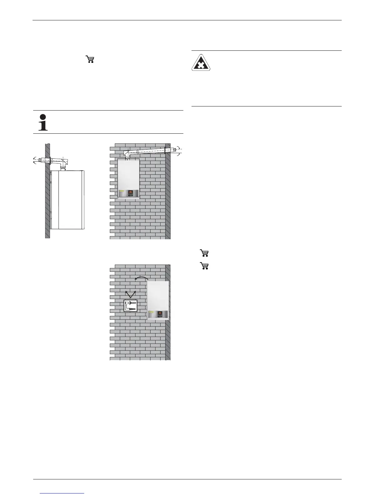
The breakthrough for the flue gas pipe must be created
so that a constant flue gas pipe of >3° to the flue gas
inspection elbow on the ROTEX GW is ensured.
Fig. 4-8 Flue gas gradient for
rear wall breakthrough
Fig. 4-9 Flue gas gradient for
side wall breakthrough
Ɣ Mount the plugs and fixing
hooks supplied in the wall.
Ɣ Hang the ROTEX GW
from the fixing hooks on
the wall.
Check that the unit is hori-
zontal.
Fig. 4-10 Wall fixture
 Loading...


