34
FA ROTEX GW - 09/2012
7 x Gas burner
7.3 Burner setting
The gas burner on the ROTEX GW is set to the gas type natural
gas E/H (G20 - 20 mbar) in the factory. If the unit is to be operated
with natural gas LL/L or liquid gas, it must first be changed over
to this type of gas by fitting the appropriate insert in the gas valve
(included in the delivery, see tab. 7-3) and the burner setting
must be checked.
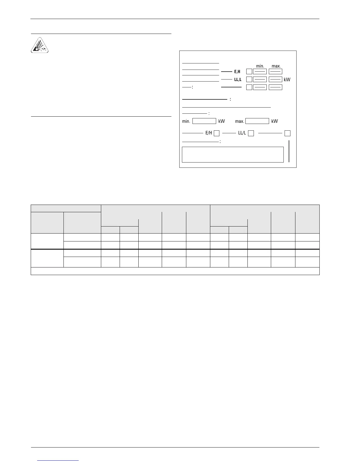
If changes to the performance settings of the burner or a
changeover to a new gas type must be made, these changes
must be documented in the operating manual and entered onto
the settings type plate (fig. 3-3, item 28).
The changeover must be provided with the date of implemen-
tation and the signature of the installer.
7.3.1 Setting values
7.3.2 Checking and setting the burner
The gas burner has been factory-set for a certain gas type. The
preset gas type and the designated gas inlet pressure are
indicated on the type identification plate under the sound
deadening hood.
Checking the burner output with the special function "emission
measurement" and using a flue gas analyser
– at maximum (full) load = 100 %,
– at minimum (base) load = 0 %.
If the emission measurement is activated (see chapter 6.7.1) the
boiler can be operated manually between full load and base load.
These settings can be individually adapted within the permitted
limits (see tab. 7-1) to the system requirements.
Auxiliary resources
– Flue gas analysis device.
– Pressure meter for measuring gas pressure.
Checking and setting (observe the sequence)
1. Inspect the pre-settings, so that the burner is set to the correct
gas type and the correct gas inlet pressure.
If the test gas indication on the type identification plate varies
from the test gas associated to the available gas type or if the
stated value deviates from the permissible gas inlet pressure,
the burner must be converted to the local conditions (see
chapter 7.3.3 to 7.3.6).
2. Turn the screw in the gas inlet pressure measuring
connection (fig. 7-1, item 9) anticlockwise by half a turn and
push up the measuring hose of the pressure meter.
3. Open the gas isolating valve.
4. Measure the gas inlet pressure (idle pressure) and compare
it with the target value (according to tab. 12-4). Leave the
measuring instrument connected.
Î If the gas inlet pressure (resting pressure) is outside the
set value range: Inform your gas supply company or
check the pressure regulator (for liquid gas).
5. Open the heating valves.
DANGER OF EXPLOSION!
Escaping gas is a direct threat to human health and
safety. Even a few sparks can cause major explo-
sions.
Ɣ Always close the gas stopcock of the house before
working on gas-conducting parts.
Ɣ If you can smell gas, air the room thoroughly. Do
not kindle any open fire or operate any electrical
switches.
Ɣ Only heating specialists authorised and trained by
the gas or power supply company should be
allowed to work on gas-conducting parts.
Fig. 7-2 Settings type plate
ROTEX GW type GW 22C GW 26C
Gas type
(Test gas)**
Setting for con-
trol -measure-
ment
Power setting CO
2
-con-
tent in %
(
±0.2%)
O
2
-content
in %
(
± 0.1%)
Power setting CO
2
-con-
tent in %
(
±0.2%)
O
2
-content
in %
(
± 0.1%)
Blower speed Load in
kW
Blower speed Load in
kW
in % in 1/min in % in 1/min
Natural gas E,H
LL, L (G20/G25)
Full load 100 5500 21.6 9.4 4.2 100 6100 26.2 9.6 3.8
Basic load 0 1500 4.5 9.0 4.9 0 1650 5.8 8.9 5.1
Liquid petrole-
um gas*
(G30/G31)
Full load 100 5300 21.6 10.9 4.3 100 6000 26.2 10.9 4.3
Basic load 0 1400 4.5 10.4 5.1 0 1600 5.8 10.5 5.0
* For changeover to liquid petroleum ** Compare details on type identification plate ROTEX Factory settings
Tab. 7-1 Flue setting values and speed limits for ROTEX GW for various different gas types
 Loading...


