9
FA ROTEX GW - 09/2012
4 x Installation
4 Installation
Incorrect erection and installation would render the manufac-
turer's guarantee for the unit void. If you have questions, please
contact our Technical Customer Service.
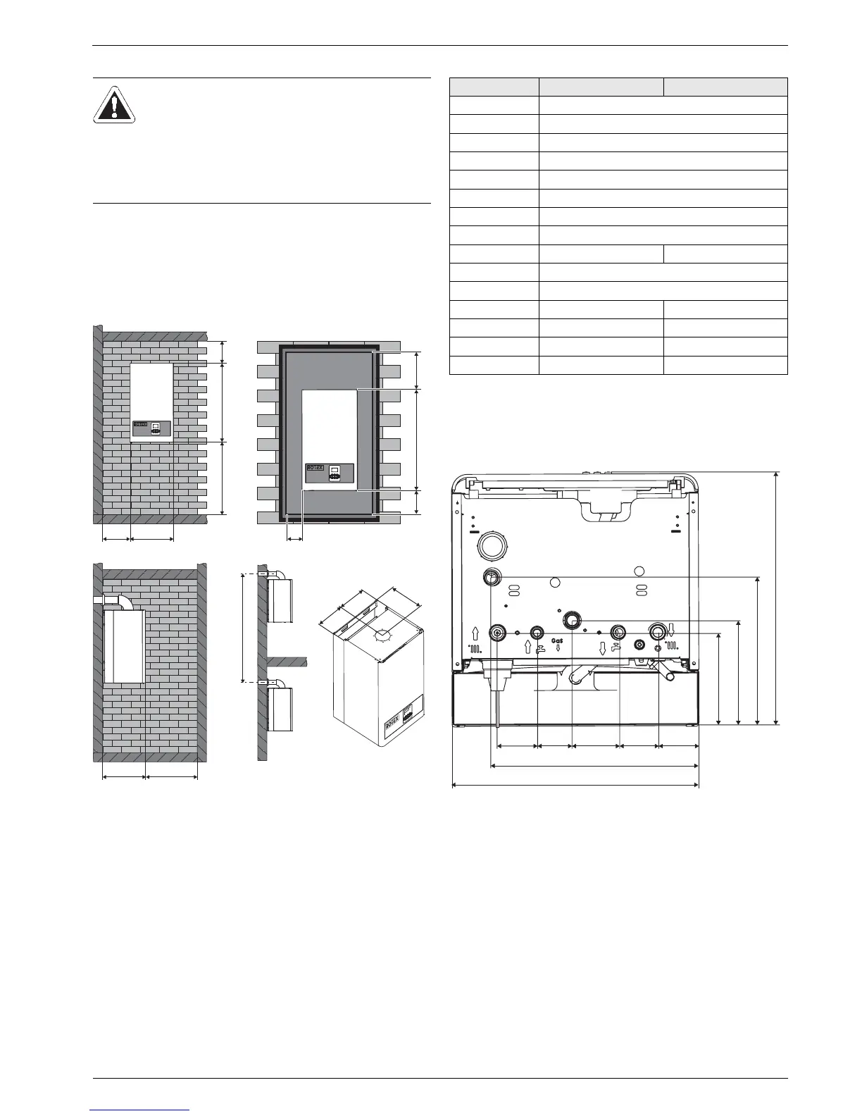
4.1 Dimensions and connection dimensions
Tab. 4-1 Fitting and connection dimensions (referred to fig. 4-1, fig. 4-2)
Connecting dimensions for the heating and hot water
connections
WARNING!
Incorrectly erected and installed gas devices may not
operate properly and are dangerous for the health and
life of individuals.
Ɣ The ROTEX GW must be erected and installed
only by heating technicians authorised and trained
by gas or energy supply companies.
A Front view on wall
B Front view in wall box
C View from left in recess
D View from left, 2 units in
separate storeys one above
the other
E Top view
Fig. 4-1 Mounting dimensions (values see tab. 4-1)
Dim. GW 22C GW 26C
b405mm
h1 733 mm
h2 t1500 mm
h3
(1
t370 mm
h4 t200 mm
h5 t2500 mm
r1 195 mm
r2 210 mm
r3 205 mm 245 mm
s1 t50 mm
s2 t400 mm
t1 345 mm 410 mm
t2 120 mm 150 mm
t3 140 mm 170 mm
t4 200 mm 245 mm
(1 Only valid for flue connection through the wall.
A Heating return (cold)
(3/4" male)
B Cold water (1/2" male)
C Gas connection (3/4" male)
D Hot water (1/2" male)
E Heating flow (hot) (3/4" male)
F Condensate drain (hose con-
nection, Ø 18/24)
G Drain valve boiler body (hose
connection, Ø 12)
Fig. 4-2 Connection dimensions for gas and water (view from below)
(see values tab. 4-1)
 Loading...


