20
FA ROTEX GW - 09/2012
4 x Installation
4.9 Connect the gas line, check the burner
setting for gas type
4.9.1 Important instructions for gas connection
Gas connection
– Implement the gas connection according to the technical
rules for gas installation, as well as the appropriate regula-
tions of the country of destination and the gas supply com-
pany.
– A thermally triggered blocking device (TAE) and a gas flow
monitor (GSW) with a DVGW inspection symbol must be fit-
ted. The TAE must comply with the test basis of DVGW-VP
301. The dimensions of the GSW must comply with the max-
imum adjustable rated load of the device.
Gas type
– The preset gas type and the designated gas inlet pressure
are indicated on the type identification plate and on the setting
type identification plate on the burner housing.
– Observe permitted gas inlet pressure (Resting pressure).
4.9.2 Connecting the gas line
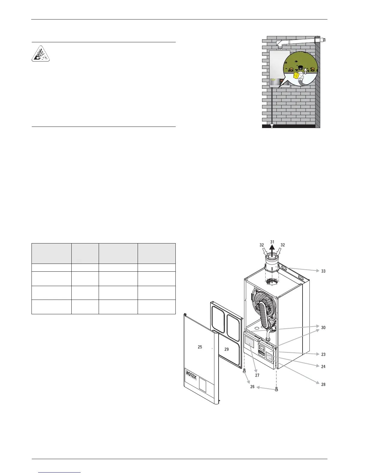
4.9.3 Access to the inside of the unit
For repair and installation purposes, or for setting and test work,
you first need to carry out the following working steps to gain
access to the internal components (see also fig. 4-17);
Ɣ Switch off the unit and secure against restart.
Ɣ Unscrew the locking screws (item 26) for the sound
deadening hood.
Ɣ Unhook the sound deadening hood (item 25) at the top and
remove it.
Ɣ Fold the switchboard with controller (item 24) downwards.
Ɣ Open the clamping lever (item 30) on the boiler cover.
Ɣ Unhook the boiler cover (item 29) at the top and remove it.
The assembly is carried out in reverse order.
DANGER OF EXPLOSION!
Escaping gas is a direct threat to human health and
safety. Even a few sparks can cause very serious
explosions.
Ɣ Always close the gas stopcock of the house before
working on gas-conducting parts.
Ɣ If you can smell gas, ventilate the room thoroughly.
Do not fan any open fire or operate any electrical
switches.
Ɣ Only heating specialists authorised and trained by
the gas or power supply company should be
allowed to work on gas-conducting parts.
Gas type Rated
pressure
in mbar
Min. inlet
pressure in
mbar
Max. inlet
pressure in
mbar
Natural gas E/H 20 18 25
Natural gas
L/LL
2)
20 18 25
Liquid petroleum
gas
1)
50 42.5 57.5
Liquid petroleum
gas B/P
1)
28-30 / 37 25 35 / 45
1) When changing over to liquid petroleum gas, the subsequent burn-
er adjustment must be adapted to the permissible gas input pres-
sure. This adaptation must be made clear by an entry on the type
identification plate (fig. 4-17, item 27) and on the setting type iden-
tification plate (fig. 4-17, item 28).
2) When changing over to natural gas LL/L, this adaptation must be
made clear by an entry on the setting type identification plate
(fig. 4-17, item 28).
Tab. 4-4 Permitted gas inlet pressure
Ɣ Connect the gas supply line
without tension to the gas
connection on the ROTEX
GW (pipe thread
DIN EN 2999 Rp 3/4").
Fig. 4-16 Gas connection
Fig. 4-17 Access to the inside of the unit (key see tab. 3-1)
 Loading...


