19
FA ROTEX GW - 09/2012
4 x Installation
Connection plan - internal regulation system
4.8 Temperature sensors and other sensors
4.8.1 General instructions for the temperature
sensors
The ROTEX GW has the facility for weather-directed control of
the flow temperature. For this function, an exterior temperature
sensor (not included with the ROTEX GW) is required.
The temperatures captured by the unit's internal temperature
sensors (flow and return flow temperature sensor, flue gas
temperature sensor, hot water temperature sensor) are used for
the output control of the burner and for fault detection. They are
already factory-connected and can be plugged directly to the
respective sensor, if they are to be swapped.
4.8.2 Other sensors
Additional information about the operating status for output
control and fault detection is provided by an integrated flow
sensor,a pressure sensor and a safety temperature switch.
They are already factory-connected and can be plugged directly
to the respective sensor, if they are to be swapped.
4.8.3 Connect the outside temperature sensor
(accessories)
Ɣ Mount the outside temperature sensor TA-GW
( 15 00 42) in such a way that the cable outlet is directed
downwards (prevents penetration of moisture).
– Choose a location at about one third of the building height
(minimum distance from floor: 2 m) at the coldest side of
the building (North or North-East).
– Thereby, exclude the proximity of external heat sources
(chimney, air shafts) and direct sunshine.
Ɣ Create access to the unit internals (see chapter 4.9.3).
Ɣ Lay the sensor line (twin core cable, minimum cross section
1mm
2
) and connect to the controller on the ROTEX GW at
the terminal rail X5 to the connections 11 and 12
(see fig. 4-15).
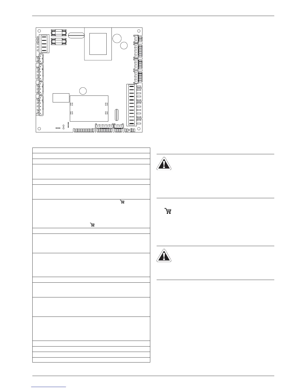
Fig. 4-15 Switchboard PCB on the internal controller
F1, F2 Fuse (T3,15 H250 - EN 60127)
X0 Earth
X1 Not assigned
X2/1-3 Hot water flow sensor
X2/4-5 Not assigned
X2/6-7 Safety temperature switch
X3 Not assigned
X4/1-2 Flow temperature sensor
X4/3-4 Return temperature sensor
X4/5-6 Flue gas temperature sensor
X5/1-2 Room station (accessories: GW-QAA73, 15 00 41)
X5/3-4 If no room station is connected: Bridge
Alternative Room thermostat or timer
X5/5-10 Not assigned
X5/11-12 Outside temperature sensor
(accessories: TA-GW, 15 00 42)
X6 Speed control burner blower
X7/1-2 Not assigned
X7/3-4 Hot water flow sensor
X7/5-7 Water pressure sensor
X7/8-9 Hot water temperature sensor
X8/1 Mains connection 230 V - L1
X8/2 Mains connection 230 V - N
X8/3 Not assigned
X8/4 Neutral output 230 V - L1 *
X8/5 Neutral output 230 V - N *
X9 Not assigned
X10/1 3-Way diverter valve - L1
X10/2 3-Way diverter valve - N
X10/3 3-Way diverter valve - L2
X11/1 Burner blower - L
X11/2 Burner blower - N
X11/3 Heating circulation pump - L
X11/4 Heating circulation pump - N
X12/1 Gas valve - L
X12/2 Gas valve - N
X12/3 Ignition transformer - L
X12/4 Ignition transformer - N
X12/5 Ionisation electrode
X13 Not assigned
X15 Not assigned
X16 Not assigned
* e.g. actuation of external circulation pump
Tab. 4-3 Connection allocation switchboard PCB (key for fig. 4-15)
 Loading...


