21
FA ROTEX GW - 09/2012
4 x Installation
4.9.4 Checking burner pre-setting
Ɣ The available gas type should be compared with the set gas
type (see type identification plate fig. 4-17, item 27).
Î The two gas types must match.
Ɣ If the burner is not labelled for the available gas type,
convert the burner over to the new gas type and label it
(see chapter 7.3 "Burner setting").
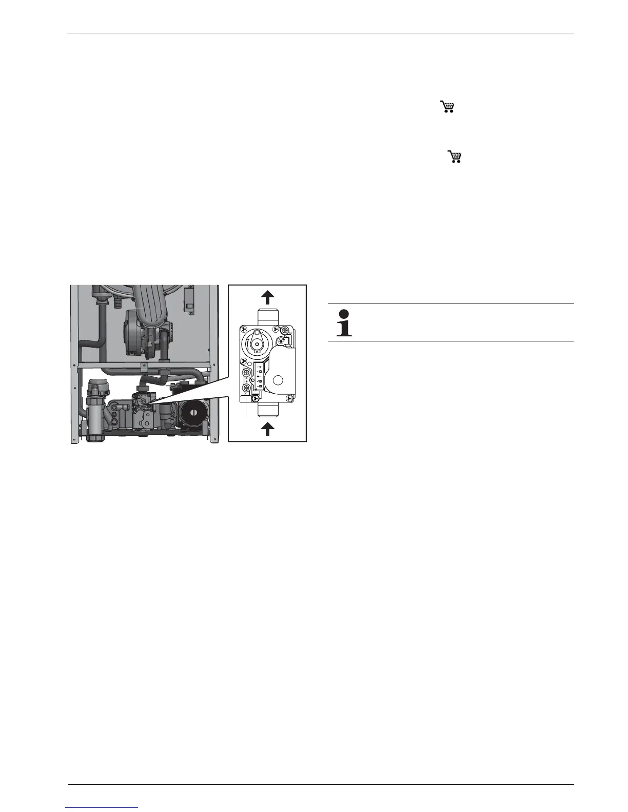
Ɣ Check the gas inlet pressure.
Ɣ Create access to the unit internals (see chapter 4.9.3).
Ɣ Release the screw (fig. 4-18, item 1) by half a turn and
push the test hose over the test connection.
Î If the gas inlet pressure lies below the permissible range
(tab. 4-4), inform the responsible gas supply company.
Î For liquid gas: Check the pressure reducer or adjust the
burner to the permissible gas inlet pressure (see
chapter 7 "Gas burner"). When changing over to liquid
petroleum gas, the subsequent burner adjustment must
be adapted to the permissible gas input pressure.
This adaptation must be made clear by an entry on the
type identification plate (fig. 4-17, item 27) and on the set-
ting type identification plate (fig. 4-17, item 28).
4.10 Optional connections
4.10.1 External temperature sensor
The ROTEX GW has the facility for weather-directed control of
the flow temperature. For this function you will need the outside
temperature sensor TA-GW ( 150042) which is connected
directly to the controller (see chapter 4.8.3).
4.10.2 Room station
The room station GW-QAA73 ( 15 00 41) can be used to
display and change all temperature values and operating modes
on the ROTEX GW.
The room station GW-QAA73 can be installed in a suitable place
in the building and can be used to remotely operate the boiler
control unit.
Ɣ Create access to the unit internals (see chapter 4.9.3).
Ɣ Lay the OpenTherm interface line (twin core, swappable,
50 m, max. 2x5 cable resistance) and connect to the
controller of the ROTEX GW at the terminal rail X5 to the
connections 1 and 2 (see fig. 4-15).
Ɣ Remove the existing cable bridge on the terminal rail X5 at
the connections 3 and 4.
Fig. 4-18 Check the gas inlet pressure.
 Loading...


