LOGO! Manual
A5E00067781 01
172
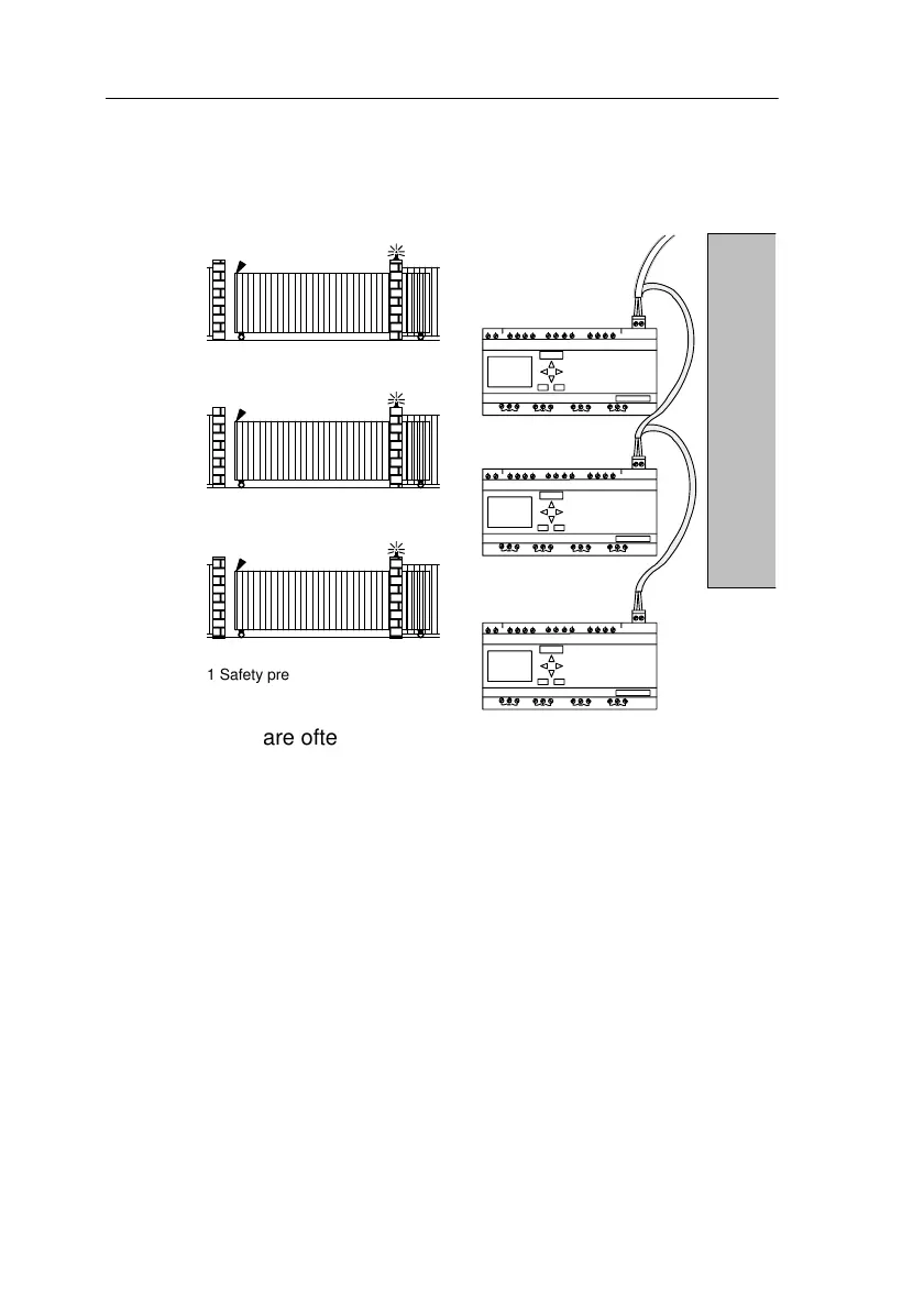
8.5 Centralized Activation and Surveillance
of Several Industrial Gates
1 Safety pressure bar 2
Flashing warning light
ASi master
1
2
1
2
1
2
There are often a number of different entrances to a com-
pany’s premises. Not all gates can always be surveilled
directly by a member of staff. They must therefore be able
to be surveilled and operated by a gateman who sits in a
central control room.
It is also important to ensure that a member of staff can
open and close the gate directly at the gate.
A LOGO!230RCLB11 is used for each gate. The modules
are linked to each other and an ASi master by means of the
ASi bus.
In this chapter, we will describe the gate control system
used for a gate. All the other gate control systems are iden-
tical.
Applications
 Loading...