19
LOGO! Manual
A5E00067781 01
2.2.3 Connecting Outputs
LOGO! ...R...
The outputs of LOGO! ...R... are relays. The contacts of
the relays are isolated from the power supply and from the
inputs.
Prerequisites for relay outputs
You can connect different loads to the outputs such as
lamps, fluorescent tubes, motors, contactors etc. The loads
connected to LOGO! ...R... must have the following proper-
ties:
The maximum switched current depends on the type of
load and the number of operations. You will find more
information on this in the technical specifications.
When switched on (Q = 1), the maximum current is
10 amperes (8 A at 230 V AC) for a non-inductive load
and 3 amperes (2 A at 12/24 V AC/DC) for an inductive
load.
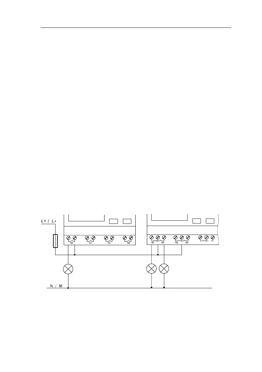
Connecting
To connect the load to LOGO! ...R...variants, proceed as
follows:
Protection with automatic circuit breaker (max. 16 A, B16, e.g. power circuit
breaker 5SX2 116-6 (if desired)
Load Load
Load
Installin
and Wirin
LOGO!
 Loading...