LOGO! Manual
A5E00067781 01
88
4.4.5 Latching Relay
Brief description
The output Q is set via the input S. The output is reset via
the input R.
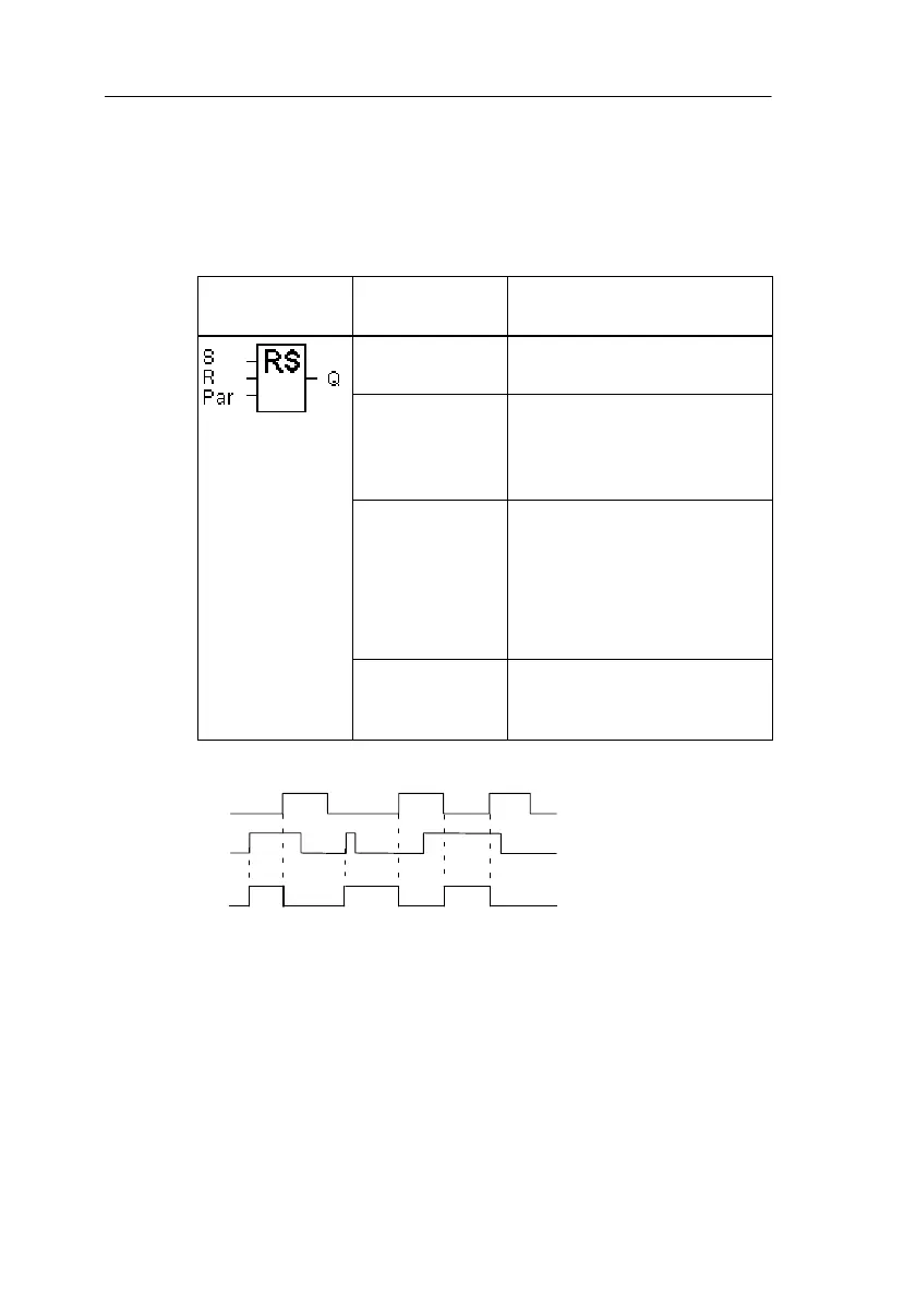
Symbol in
LOGO!
Connection Description
Input S Input S sets the output Q
to 1.
Input R The input R resets the out-
put Q to 0. If S and R are
both 1 at the same time,
then the output is reset
Parameter Par This parameter is used to
switch retentivity on or off.
Rem:
off = no retentive feature
on = the state can be stored
retentively
Output Q Q switches on when S does
and remains on until the in-
put R is set.
Timing diagram
S
R
Q
Switching behavior
A latching relay is a simple binary memory cell. The signal
at the output depends on the states of the inputs and the
previous state at the output. The following table illustrates
the logic once more:
LOGO! Functions
 Loading...