115
LOGO! Manual
A5E00067781 01
4.4.17 Analog Trigger
Brief description
The output is switched on, if the analog value exceeds a
parameterizable on threshold. The output is switched off if
the analog value falls below the parameterizable off thresh-
old (hysteresis).
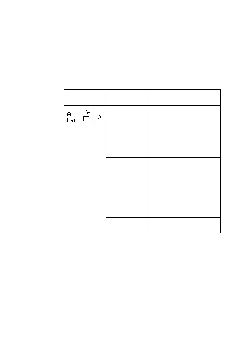
Symbol in
LOGO!
Connection Description
Input Ax At the output Ax, apply the
analog signal to be evalu-
ated.
Use the connectors I7 (AI1)
or I8 (AI2).
0-10 V corresponds to
0-1000 (internal value).
Parameter Par:
, , SW,
SW
: Gain in %
Value range 0..1000 %
: Offset
Value range 999
SW: on threshold
Value range 19990
SW: off threshold
Value range 19990
Output Q Q is set or reset depending
on the threshold values.
Gain and Offset parameters
Refer to the information in Section 4.3.6 on the Gain and
Offset parameters.
LOGO! Functions
 Loading...