LOGO! Manual
A5E00067781 01
14
2.2.2 Connecting LOGO!’s Inputs
Prerequisites
Connect sensors to the inputs. The sensors may be push-
buttons, switches, photoelectric barriers, daylight control
switches etc.
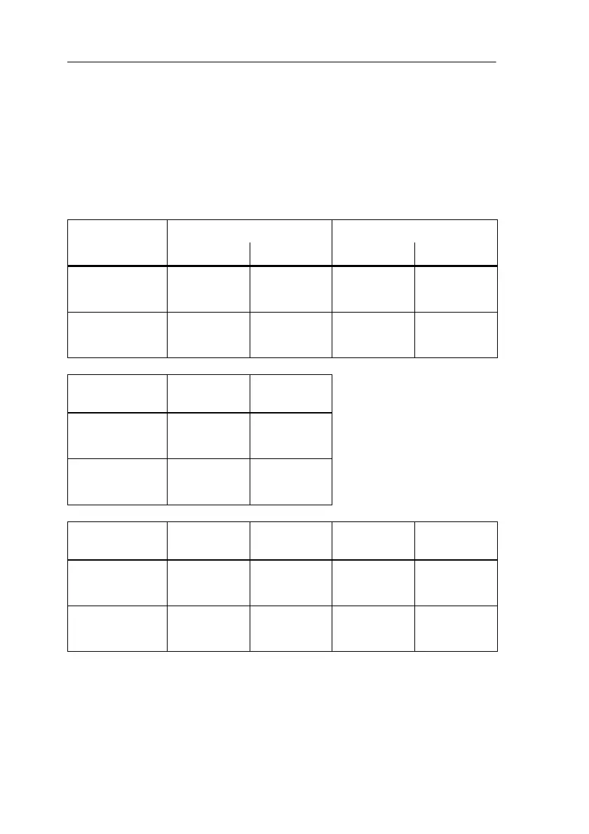
Sensor attributesfor LOGO!
LOGO! 12/24 RC/RCo LOGO! 24
I1 ... I6 I7, I8 I1 ... I6 I7, I8
Circuit state 0 < 5 V DC < 5 V DC < 5 V DC < 5 V DC
Input current < 1.0 mA < 0.05 mA < 1.0 mA < 0.05 mA
Schaltzustand 1 > 8 V DC > 8 V DC > 8 V DC > 8 V DC
Input current > 1.5 mA > 0.1 mA > 1.5 mA > 0.1 mA
LOGO! 24
RC/RCo (AC)
LOGO! 230
RC/RCo
Circuit state 0 < 5 V AC < 40 V AC
Input current < 1.0 mA < 0.03 mA
Circuit state 1 > 12 V AC > 79 V AC
Input current > 2.5 mA > 0.08 mA
LOGO! 12
RCL
LOGO! 24
L
LOGO! 24
RCL...
LOGO! 230
RCL...
Circuit state 0 < 4 V DC < 5 V DC < 5 V DC < 40 V AC
Input current < 0.5 mA < 1.5 mA < 1.5 mA < 0.03 mA
Circuit state 1 > 8 V DC > 12 V DC > 12 V DC > 79 V AC
Input current > 1.5 mA > 4.5 mA > 4.5 mA > 0.08 mA
Installin
and Wirin
LOGO!
 Loading...