15
LOGO! Manual
A5E00067781 01
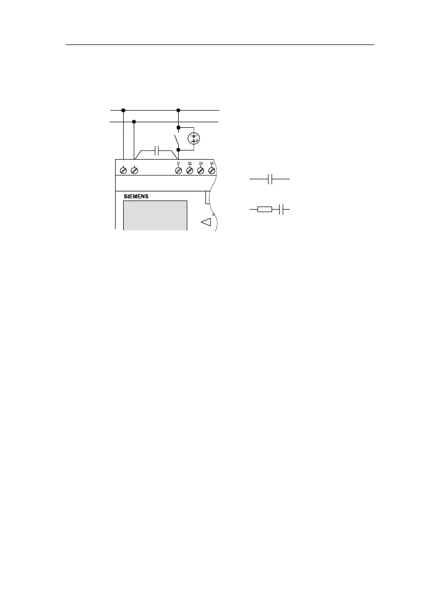
Sensor connections
Connecting glow lamps, 2-wire proximity switch for
LOGO! 230RC/230RCo
L1
N
NL1
C
3SB1430-3C
3SB1420-3D
3TX7462-3T
Order number for C:
Siemens
Switching Devices & Systems
Circuit state change 0 1 / 1 0
When the circuit state changes from 0 to 1, circuit state 1
and, in the case of a change from 1 to 0, circuit state 0
must be in place for at least one program cycle for LOGO!
to recognize the new circuit state.
The cycle time of the program processing depends on the
size of the program.
In the appendix you can find a description of a short test
program that will help you to work out the current cycle
time.
Fast inputs
LOGO! (apart from LOGO! 230..., 24 RC and 24 RCo) also
has inputs for frequency functions. The same restrictions
do not apply to these fast inputs. The fast inputs are the
last two inputs on a LOGO!:
LOGO! Standard variant: inputs I5/I6
LOGO!...L variant: inputs I11/I12
Installin
and Wirin
LOGO!
 Loading...