LOGO! Manual
A5E00067781 01
40
>Edit Prg
Clear Prg
Set Clock
ASi_BUS..
LOGO!’s programming menu
The ASi bus entry only appears
with LOGO!...LB11 variants
Here too, you can move the ”>” by pressing the and
keys. Position the ”>” on ”Edit Prg” (i.e. to enter the pro-
gram) and press OK. LOGO! then displays the first output:
LOGO!’s first output
Q1
Use the keys and keys to select the other outputs. At
this point, you begin to enter your circuit.
3.6.2 First Program
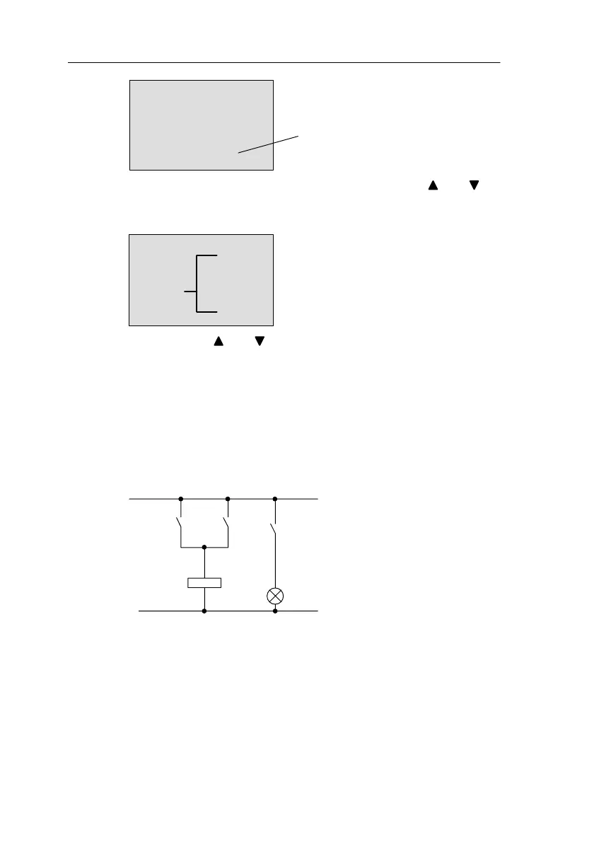
Let’s have a look at the following circuit: a parallel connec-
tion of two switches.
Circuit diagram
How a circuit is represented in a circuit diagram
K1
S1
K1
S2
E1
The consumer is switched on
by switch S1 or switch S2. As
far as LOGO! is concerned,
the parallel connection of the
switches is an OR block be-
cause S1 or S2 switches the
output on.
Pro
rammin
LOGO!
 Loading...