71
LOGO! Manual
A5E00067781 01
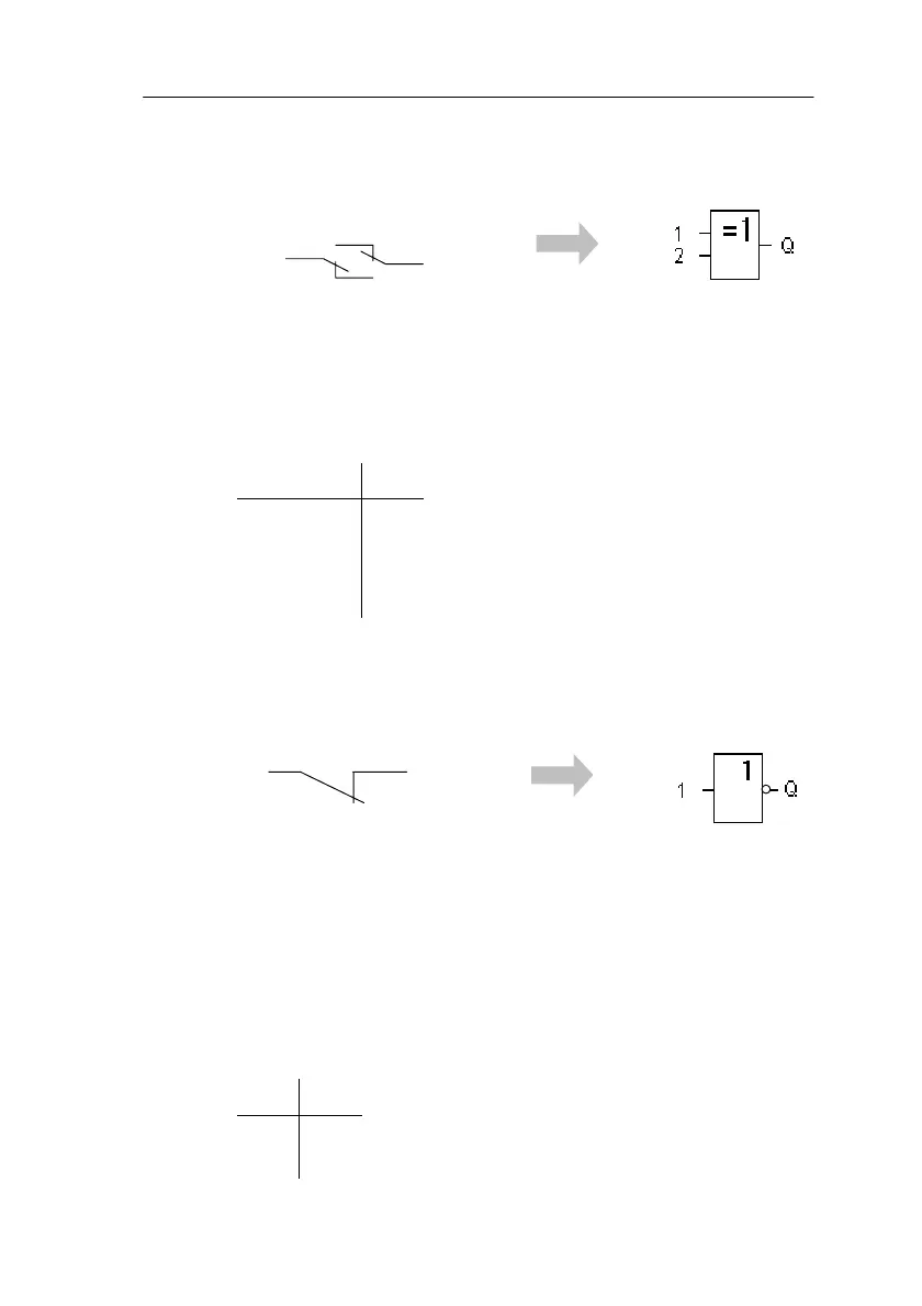
4.2.7 XOR (Exclusive OR)
An XOR in a circuit diagram is a
series connection of two change-
over contacts:
Symbol in LOGO!:
The output of XOR adopts the state 1 if the inputs have
different states.
If an input pin of this block is not wired (x), then the follow-
ing applies to the input: x = 0.
Logic table for XOR
12Q
0 0 0
011
101
110
4.2.8 NOT (Negation, Inverter)
A normally closed contact is repre-
sented in a circuit diagram as follows:
Symbol in LOGO!:
The output adopts the state 1 if the input has the state 0. In
other words, NOT inverts the state at the input.
The advantage of the NOT function can be illustrated by
the following example: you no longer require normally
closed contacts for LOGO! You use a normally open con-
tact and convert it into a normally closed contact by using
NOT.
Logic table for NOT
1Q
0 1
10
LOGO! Functions
 Loading...