LOGO! Manual
A5E00067781 01
22
Connecting
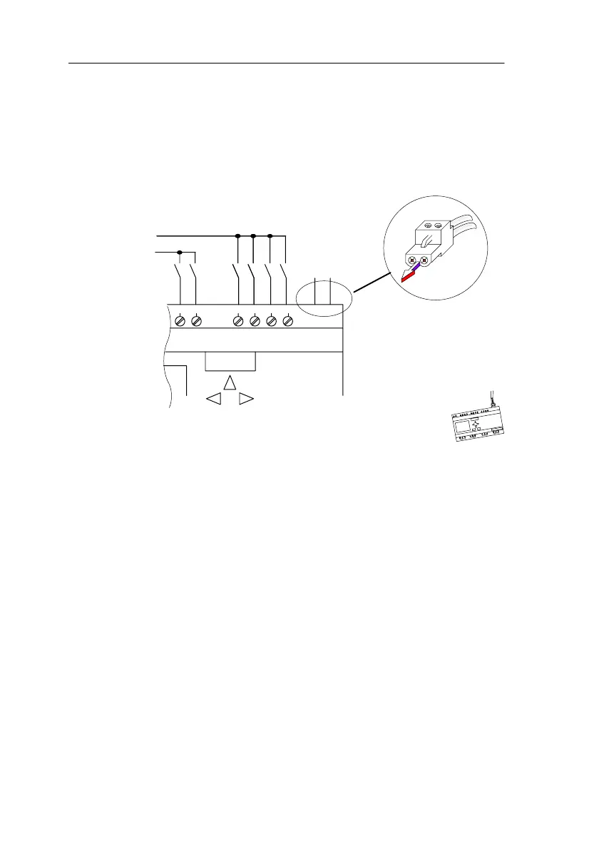
Connect the bus connection cable to the connector pro-
vided or to a connector permitted by the system. Make
sure that the polarity is correct.
Then push the wired connector into the interface marked
AS interface.
LOGO!
L1
LOGO!...B11
L1
L2
+-
AS interface
-+
2.2.5 LOGO!...B11 on the ASi Bus
LOGO!...B11 must be known to the bus master if you are
to be able to use the ASi functionality. This takes places
automatically when you connect LOGO!...B11 to the bus
lead. The master detects the address of the slave.
In the case of LOGO!...B1, the address preset at the fac-
tory = 0. The master assigns a new address that is not
equal to 0.
If there are no address conflicts in the system or if only one
slave with the address 0 is connected, you do not have to
take any further steps.
Installin
and Wirin
LOGO!
 Loading...