 Loading...
Do you have a question about the Siemens LOGO! 24 and is the answer not in the manual?
| Dimensions | 90 x 72 x 55 mm |
|---|---|
| Relay Outputs | 4 |
| Programming | LOGO! Soft Comfort |
| Mounting Type | DIN Rail |
| Protection Class | IP20 |
| Inputs | 8 Digital |
| Outputs | 4 Relay |
| Output Current | 10 A per relay output |
| Operating Temperature | 0 ... 55 °C |
| Display | LCD with backlight |
Information on how to install, program, and use LOGO! devices.
Guidance on finding answers to LOGO! questions via the Internet.
Explains danger, warning, caution, and note symbols and their meanings.
Specifies qualified personnel and proper usage guidelines for the LOGO! device.
Definition and core components of Siemens LOGO! universal logic module.
Overview of available LOGO! models, their features, and dimensions.
Step-by-step instructions for mounting LOGO! on a DIN rail and its removal.
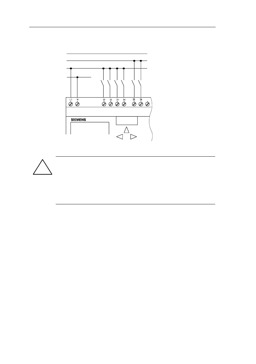
Procedures for connecting power supply, inputs, outputs, and ASi bus to LOGO!.
Explanation of LOGO! inputs, outputs, connectors, and the concept of blocks.
Step-by-step guide to entering programs, switching modes, and starting execution.
Essential rules for efficient LOGO! programming, including planning and cursor usage.
Overview of fundamental logic operations like AND, OR, NAND, NOR, XOR, NOT.
Introduction to special functions, their input types, and background information.
Details on time-related functions (On/Off Delay) and counter functions (Up/Down, Hours).
Procedure to enter parameterization mode for adjusting block settings without program changes.
Information on yellow (copying) and red (protection) program modules for data storage.
Procedures for transferring programs between LOGO!, modules, and PCs.
Capabilities of LOGO!Soft Comfort for offline programming, simulation, and documentation.
Steps required to establish a PC connection to LOGO! for programming and data transfer.
Introduction to various application examples for LOGO! in different industries.
Environmental, mechanical, and general technical data for LOGO! devices.
Detailed technical specifications for LOGO! 230RC and 230RCLB11 variants.
Detailed technical specifications for LOGO! 24 and 24RC/RCo variants.
Method for calculating the memory needs of a circuit, including an example.
Steps to create and run a test program for calculating LOGO! cycle time.
Benefits of using LOGO! variants without keypads and displays, focusing on cost and space.
Procedure to switch LOGO!...B11 variants between active and passive states via the menu.
Visual representation of the LOGO! menu hierarchy for programming and parameterization.
Table listing available LOGO! variants, accessories, and their order numbers.
Alphabetical list of abbreviations and their meanings used throughout the manual.
