29
LOGO! Manual
A5E00067781 01
LOGO!’s connectors
The term connector refers to all connections and states in
LOGO!.
The inputs and outputs can have the state ’0’ or ’1’. ’0’
means there is no voltage at the input; ’1’ means that there
is. But that is unlikely to be new to you.
We introduced the connectors hi, lo and x, in order to facili-
tate program entry for you. ’hi’ (high) has the fixed state ’1’
and ’lo’ (low) has the fixed state ’0’.
If you don’t want to wire an input on a block, use the ’x’
connector. You can find out what a block is on the next
page.
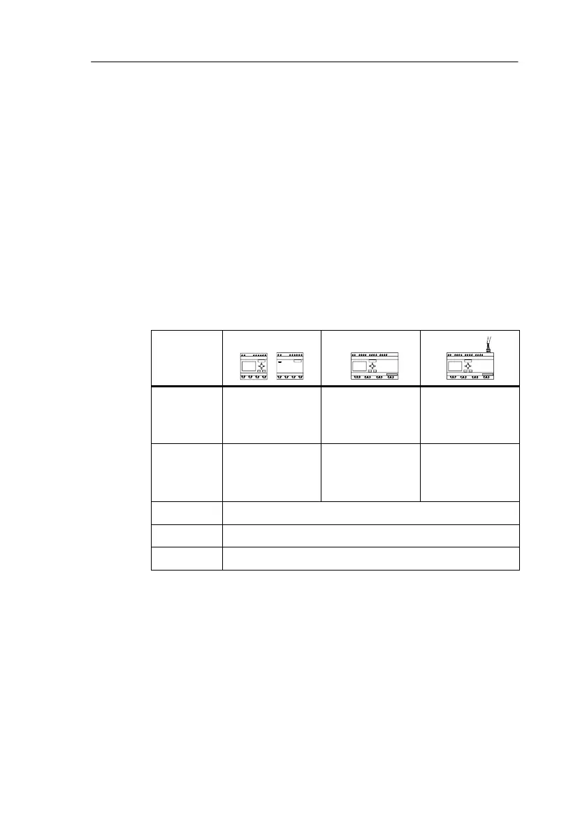
LOGO! recognizes the following connectors:
Connec-
tors
Inputs I1... I6I,
I7 (AI1),
I8 (AI2)
I1...I12 I1...I12 and
Ia1...Ia4
(AS interface)
Outputs Q1...Q4 Q1...Q8 Q1...Q8 and
Qa1...Qa4
(AS interface)
lo Signal with level ’0’ (off)
hi Signal with level ’1’ (on)
x An existing connection that is not used
Pro
rammin
LOGO!
 Loading...