31
LOGO! Manual
A5E00067781 01
Displaying a block in LOGO!
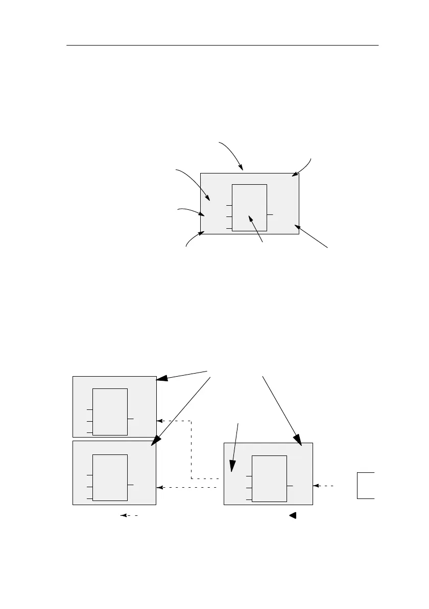
The figure below shows a typical LOGO! display. As you
can see only block can be shown at a time. We have there-
fore introduced block numbers to help you to check how
the circuit is structured.
B02
1
I2
Q1
B01
Display image of LOGO!
x
Block number –
assigned by
LOGO!
This shows that a
further block is
connected
Input
Connection is not required Output
Block
Assigning a block number
Whenever you insert a block in a program, LOGO! assigns
that block a number.
LOGO! uses the block number to indicate the connections
between the blocks. The block numbers are therefore
chiefly meant to help you find your way around the pro-
gram.
I1
I2
I3
1
B01
B02
B02
1
B03
Q1
B01
B01
Move around the program using the key
I4
I5
I6
1
B01
There is a con-
nection between
these blocks
Block number
Q1
x
B03
Pro
rammin
LOGO!
 Loading...