Installing and connecting the device
3.3 Connecting the device
SIMATIC IOT2050
34 Operating Instructions, 03/2024, A5E39456816-AF
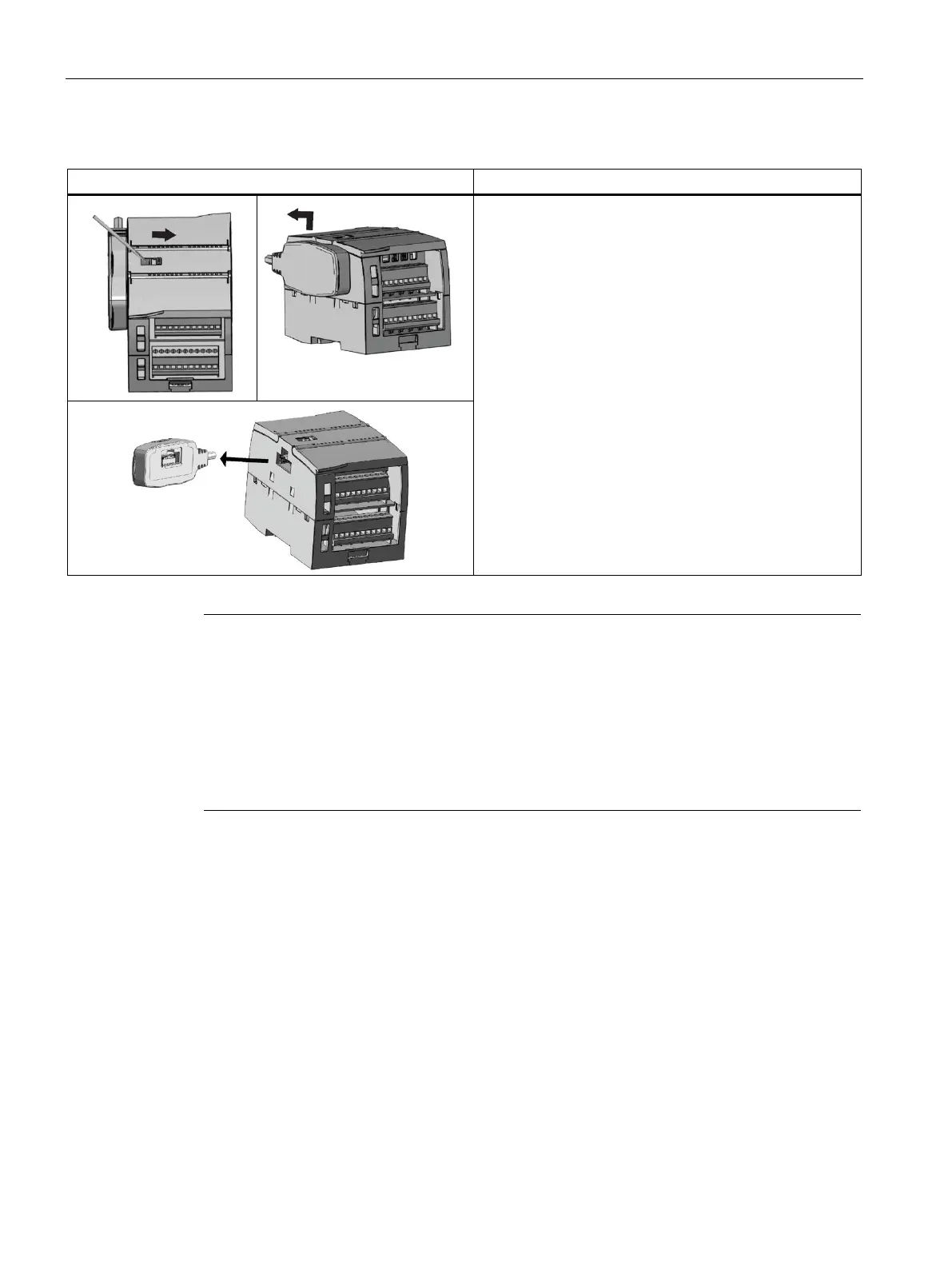
Table 3- 2 Removing the female connector of the expansion cable
1. Ensure that the CPU and all S7-1200 equipment are
disconnected from electrical power.
2. Unlock the connector:
– Place a screwdriver beside the tab on the top of the
signal module.
– Press down slightly and slide the tab fully to the
right.
3. Lift the connector up slightly to disengage the hook
extension.
4. Remove the female connector.
Installing the expansion cable in a vibration environment
If the expansion cable is connected to modules that move, or are not firmly fixed, the cable
male end snap
-on connection can gradually become loose.
Use a cable tie to fix the male end cable on the DIN
-
rail (or other place) to provide extra strain
relief.
Avoid using excessive force when you pull the cable during installation. Ensure the cable
-
module connection is in the correct position once installation is complete.
3.3.4.2 Connecting the Ethernet
To ensure the safety and protect IOT2050 SM from electrical surges, ground the Ethernet
cable as follows:
1. Strip the insulation of ethernet cable (typically within the last 10 cm of the cable).
2. Mount the earthing clamps on the DIN rail.
3. Plug the shielding of the cable into the earthing clamp.
 Loading...