Installation and connection
4.2 Installation of the HMI device
TP 270, OP 270, MP 270B (WinCC flexible)
4-2 Operating Instructions, Edition 03/2004, 6AV6691-1DD01-0AB0
Installation in front panels
The MP 270B Keys and OP 270 can be secured in the installation cut-out using spring
terminals. When secured using spring terminals, no additional holes for securing the device
are required in the front panel.
Spring terminals used in conjunction with an outer seal can achieve IP65 degree of
protection. Screwed supports achieve the degree of protection IP54.
Installing the MP 270B Keys or OP 270 in the front panel:
1. Check that the installation seal is fitted on the HMI device.
Do not mount the installation seal turned inside out. This can lead to gaps in the
installation cut-out.
2. Working from the front, insert the HMI device into the installation cut-out.
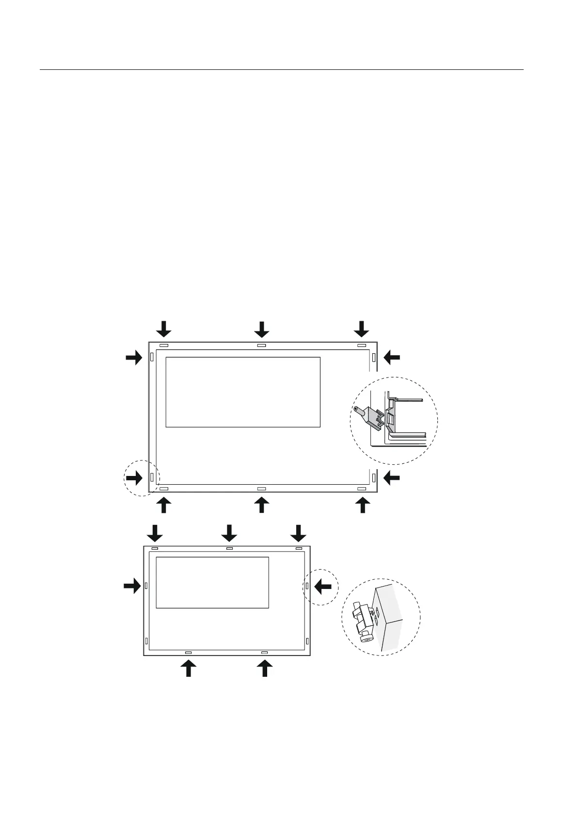
3. Insert the hooks of the spring terminals into the corresponding recesses in the housing of
the HMI device.
The individual positions are indicated in the figures below by means of arrows.
MP 270B Ke
, OP 270 10”
OP 270 6”
If necessary, the OP 270 6" can be additionally held by two further spring terminals
inserted in the two bottom recesses on the side of the HMI device. They are not supplied
with the OP 270 6" .

 Loading...