Installation and connection
4.3 Connecting the HMI device
TP 270, OP 270, MP 270B (WinCC flexible)
Operating Instructions, Edition 03/2004, 6AV6691-1DD01-0AB0
4-17
Connection configuration
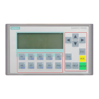
The figure below illustrates how to connect an uninterruptible power supply UPS with serial
interface to the HMI device.
IF2
UPS
RS 232
24 V
Operating unit
Figure 4-7 Connection configuration for an uninterruptible power supply
See also
UPS (Page 6-16)
Transferring options (Page 7-22)
4.3.8 Connecting the power supply
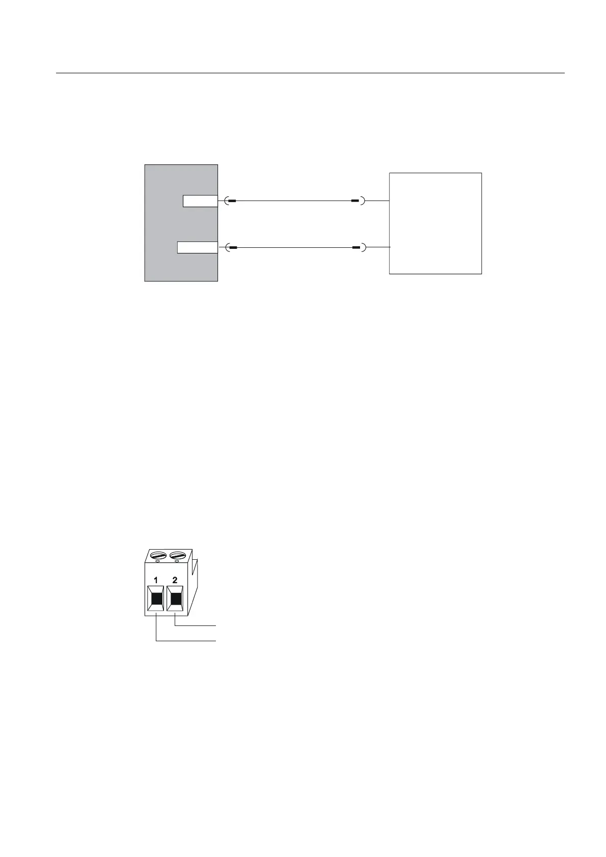
Connecting the plug-in terminal block
The power supply for the HMI device is connected at the 2-pin plug connector on the
underside of the unit. Use the 2-pin terminal block supplied for this purpose. The plug-in
terminal block is designed for cables with a cross-section not larger than 2.5 mm
2
.
The figure below illustrates the assignment of the plug-in terminal block.
GND
+ 24 V D
Ensure that the lines are connected properly to the correct terminals. Also note the labeling
for the contact pins on the back of the HMI device.
The HMI device is equipped with reverse battery protection.

 Loading...