3. Measure the winding temperature and the insulation resistance of the winding in relation
to the machine enclosure. The winding temperature should not exceed 40° C during the
measurement. Convert the measured insulation resistances in accordance with the formula
to the reference temperature of 40° C. This thereby ensures that the minimum values
specified can be compared.
4. Read out the insulation resistance one minute after applying the measuring voltage.
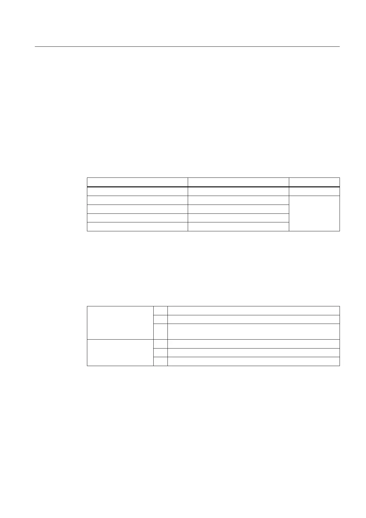
Limit values for the stator winding insulation resistance
The following table specifies the measuring voltage and limit values for the insulation
resistance. These values correspond to IEEE 43‑2000 recommendations.
Table 5-1 Stator winding insulation resistance at 40° C
V
N
[V] V
Meas
[V] R
C
[MΩ]
U ≤ 1000 500 ≥ 5
1000 ≤ U ≤ 2500 500 (max. 1000) 100
2500 < U ≤ 5000 1000 (max. 2500)
5000 < U ≤ 12000 2500 (max. 5000)
U > 12000 5000 (max. 10000)
U
rated
= rated voltage, see the rating plate
U
meas
= DC measuring voltage
R
C
= minimum insulation resistance at reference temperature of 40° C
Conversion to the reference temperature
When measuring with winding temperatures other than 40° C, convert the measuring value to
the reference temperature of 40° C according to the following equations from IEEE 43-2000.
(1)
R
C
= K
T
· R
T
R
C
Insulation resistance converted to 40° C reference temperature
k
T
Temperature coefficient according to equation (2)
R
T
Measured insulation resistance for measuring/winding temperature T
in °C
(2)
K
T
= (0.5)
(40-T)/10
40 Reference temperature in °C
10 Halving/doubling of the insulation resistance with 10 K
T Measuring/winding temperature in °C
In this case, doubling or halving the insulation resistance at a temperature change of 10 K is
used as the basis.
● The insulation resistance halves every time the temperature rises by 10 K.
● The resistance doubles every time the temperature falls by 10 K.
Mounting
5.1 Preparing for installation
SIMOTICS M-1PH8 1PH818., 1PH822.
Operating Instructions 07/2016 51
 Loading...