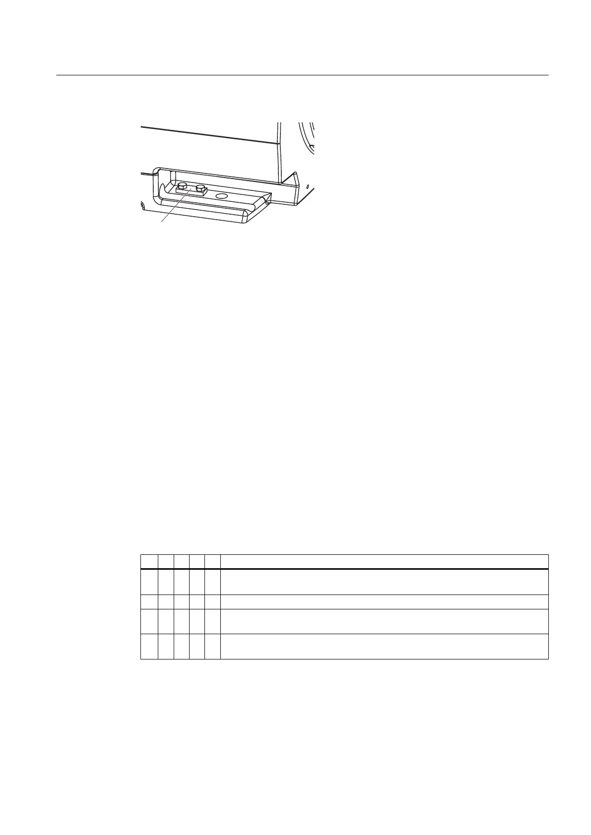
Figure 6-2 Terminal lug ① for the grounding conductor for a water-cooled motor
6.3 Connecting
Depending on the version, different terminal boxes may be installed on the machine.
Dependent on the terminal box, different cable entries and options for the cable connection
are possible. You can identify the terminal box installed on the machine via the illustrations in
the following chapters.
6.3.1 Circuit diagram
Data on the connection and connecting the motor winding can be found in the circuit diagram
in the cover of the terminal box.
6.3.2 Terminal designation
According to IEC / EN 60034‑8, the following basic definitions apply to the terminal
designations for 3-phase machines:
Table 6-1 Terminal designations using the 1U1-1 as an example
1 U 1 - 1 Designation
x Index for pole assignment for pole-changing machines where applicable. A lower
index signifies a lower speed. Special case for split winding.
x Phase designation U, V, W
x Index for winding start (1) or end (2) or if there is more than one connection per
winding
x Additional indices for cases in which it is obligatory to connect parallel power feed
cables to several terminals with otherwise identical designations
Electrical connection
6.3 Connecting
SIMOTICS M-1PH8 1PH818., 1PH822.
Operating Instructions 07/2016 69
 Loading...