Operator control (hardware)
3.1 Operator control and display elements
3.1.3 Mode selector
Mode selector positions
Note
It is recommended that SIMOTION SCOUT be used exclusively to switch the operating
modes of the module. Do to so, leave the mode selector at position 0 (RUN). The mode
selector cannot be changed mechanically when a BOP is installed. The LED display
indicates the current mode selection.
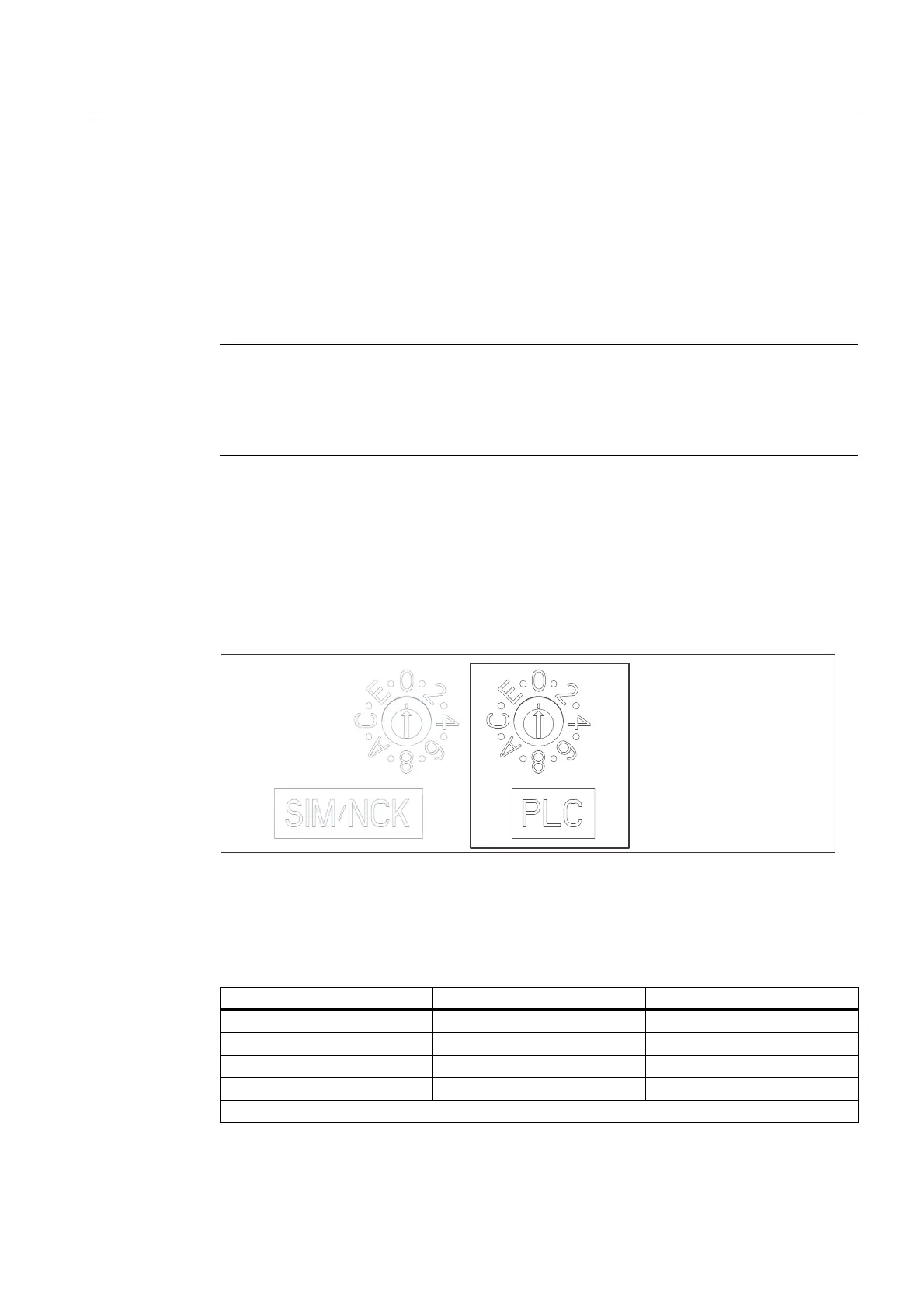
The control unit has a mode selector in the lower section of the front panel.
On the right, the selector labeled PLC is used for mode selection for the control unit.
On the left, the service selector (labeled SIM/NCK) is only relevant for service technicians.
The selector position must remain as shown (position 0).
The positions of the mode selector are explained in the order in which they appear on the
control unit.
Mode selector
Figure 3-4 Mode selector
Possible selector positions
Table 3-2 Selector positions and their meaning
Selector position Meaning LED
0 RUN RUN
1 STOPU SU/PF
2 STOP STOP
3 MRES
Other selector positions are not assigned.
D4xx
Manual, 12.2004, 6AU1900-1AJ32-0BA0
3-7

 Loading...


