Interfaces
4.4 Digital inputs/outputs
Digital inputs/outputs on X122/X132
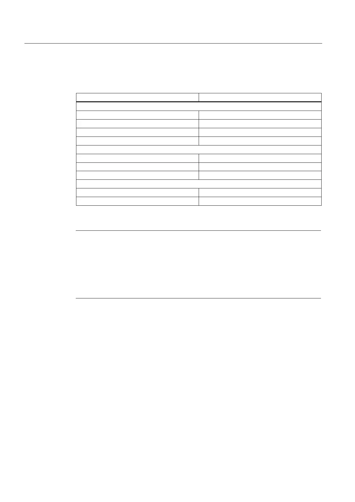
Table 4-10 Technical data of the digital inputs/output of X122/X132
parameters Values
As an input
Voltage -3 V to 30 V
Typical power consumption 10 mA at 24 VDC
Signal level (including ripple factor) High signal level: 15 V to 30 V
Low signal level: -3 V to 5 V
Pins 8, 10, and 11 are "fast inputs"
Signal propagation delays of inputs/"fast inputs" L ∀ H: 50 μs/5 μs
H ∀ L: 50 μs/100 μs
As an output
Voltage 24 VDC
Maximum load current per output 500 mA
Note
An open input is interpreted as "low."
The "fast inputs" can be used for position sensing.
Terminal M1 or M2 must be connected for the digital inputs to work. This can be done as
follows:
Connect the coupled reference ground of the digital inputs, or provide a jumper to terminal
M. (Caution: this removes the electrical isolation for these digital inputs.)
4.4.4 Use of X122 and X123 interfaces
Connecting sensors and actuators
Digital inputs and outputs can be used to connect various sensors and actuators to the two
12-pin X122 and X132 front panel connectors.
The following types of digital inputs/outputs are available:
• Digital inputs
• Bidirectional digital inputs/outputs
Assignment of the inputs/outputs to functions can be parameterized as required. Special
functions, such as input of the measuring input and output of the output cam, can be
assigned to the inputs/outputs.
D4xx
4-10 Manual, 12.2004, 6AU1900-1AJ32-0BA0

 Loading...


