Interfaces
4.4 Digital inputs/outputs
4.4.2 Pin assignment for interfaces X122 and X132
Interface assignment of X122 and X132
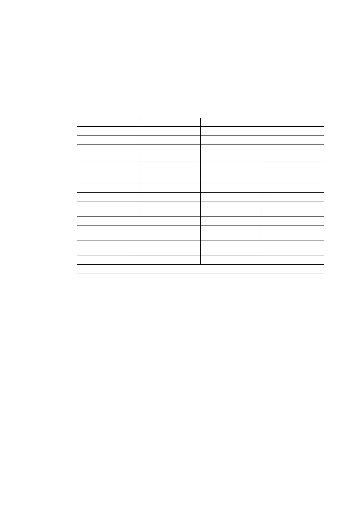
Table 4-8 X122 Digital inputs/outputs
Pin Signal name Signal type Meaning
1 DI0 I Digital input 0
2 DI1 I Digital input 0
3 DI2 I Digital input 0
4 DI3 I Digital input 0
5 M1 GND Ground for DI0 - DI3
(functionally-separated
relative to M)
6 M GND Ground
7 DI/DO8 B Digital input/output 8
8 DI/DO9 B Digital input/output 9
(fast input)
9 M GND Ground
10 DI/DO10 B Digital input/output 10
(fast input)
11 DI/DO11 B Digital input/output 11
(fast input)
12 M GND Ground
Signal type: B = Bidirectional; I = Input; GND = Reference potential (ground)
D4xx
4-8 Manual, 12.2004, 6AU1900-1AJ32-0BA0

 Loading...


