Connecting
6.9 Assignment of terminals and connectors
SINAMICS DCM DC Converter
184 Operating Instructions, 12/2018, A5E34763375A
Terminal assignment for option G63
The technical data for terminals X177_1, X177_2 and X177_5 corresponds to the
specifications for terminal X177 on the Connector Board in the version without option G63,
see Table 6-36 Assignment, terminal X177 (Page 177).
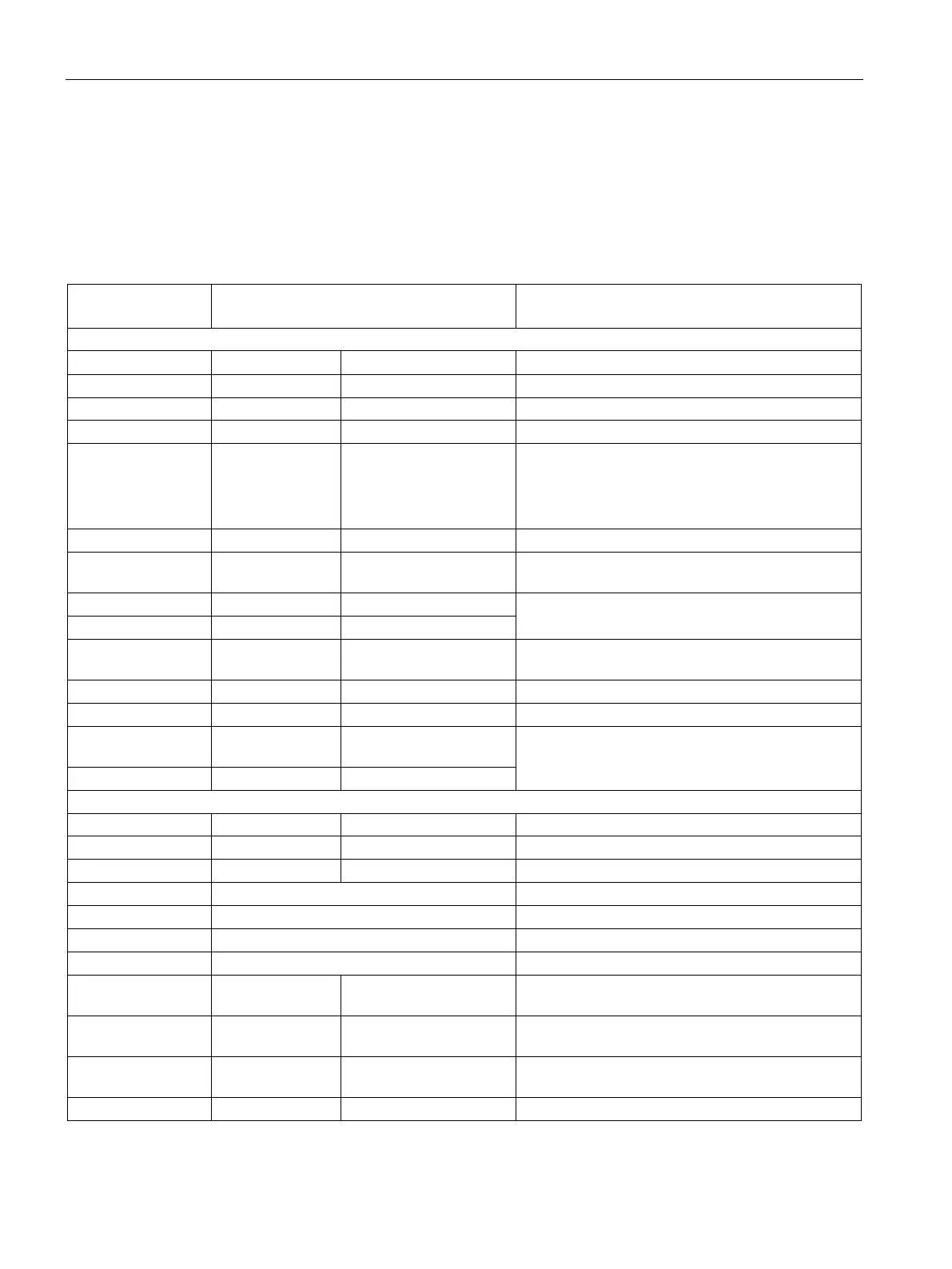
Table 6- 42 Assignment of the terminals on the Terminal Module Cabinet (TMC) (overview)
1st terminal block (X177_1)
1, 2 AI 3 +, AI 3 - Analog input 3 See X177.1 and 2
9, 10 24 V DC 24 V supply (output) 24 V DC, short-circuit proof
Max. load 200 mA (terminals 9, 10, 57, 58, 59 and
60 combined)
Internal supply to digital ground and analog ground
15, 16, 17, 18 DI/DO 4, 5, 6, 7 Digital input/output 4, 5,
See X177.15, 16, 17, 18
Digital output 0, 1, 2, 3
See X177.19, 20, 21, 22, 23, 24
25, 26 AI 0 +, AI 0 - Analog input 0, main
See X177.25 and 26
31, 32 P10, N10 Reference voltage ±10 V
See X177.31, 32, 33, 34
33, 34 M Ground, analog
2nd terminal block (X177_2)
Incremental encoder supply
Incremental encoder track 1 +/-
Incremental encoder track 2 +/-
Incremental encoder zero mark +/-
49, 50 AO 0, M Analog output 0, analog
See X177.49 and 50
51, 52 AO 1, M Analog output 1, analog
See X177.51 and 52
53, 54, 55 Temp 1, 2, 3 Temperature sensor,
See X177.53, 54, 55