Additional system components
7.4 Terminal Module TM15
SINAMICS DCM DC Converter
228 Operating Instructions, 12/2018, A5E34763375A
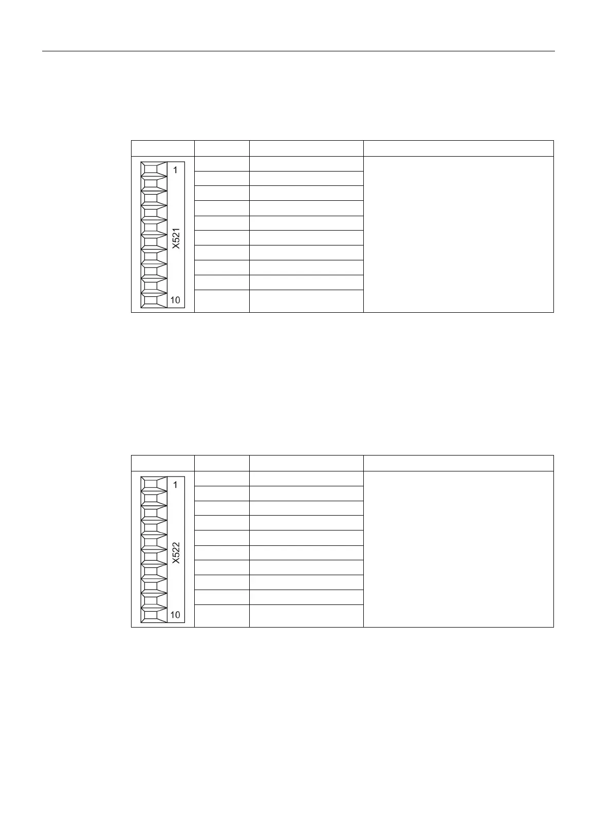
X521 bidirectional digital inputs/outputs
Table 7- 26 Screw terminal X521
See Section
"Technical specifications"
4 DI/DO 10
10 M2 (GND)
L2+: A 24 V DC power supply for DI/DO 8 to 15 (second potential group) must always be
connected if at least one DI/DO of the potential group is used as output.
M2: A ground reference for DI/DO 8 to 15 (second potential group) must always be connected if at
least one DI/DO of the potential group is used as either input or output.
DI/DO: Bidirectional digital input/output
X522 bidirectional digital inputs/outputs
Table 7- 27 Screw terminal X522
See Section
"Technical specifications"
5 DI/DO 19
10 M3 (GND)
L3+: A 24 V DC power supply for DI/DO 16 to 23 (third potential group) must always be connected
if at least one DI/DO of the potential group is used as output.
M3: A ground reference for DI/DO 16 to 23 (third potential group) must always be connected if at
least one DI/DO of the potential group is used as either input or output.
DI/DO: Bidirectional digital input/output