Functional safety
13.5 Application examples
SINAMICS DCM DC Converter
Operating Instructions, 12/2018, A5E34763375A
715
In the case of SS1 applications, the
quick stop function OFF 3
(undelayed contact block,
terminal X177.15 DI/DO 4) of
is guided via the safety relay.
Note
In the case of SS1 applications, the OFF 3 ramp of the SINAMICS DCM and the setting of
the delay time on the safety relay, must be manually set to the process and adjusted and
coordinated with one another when commissioning the system.
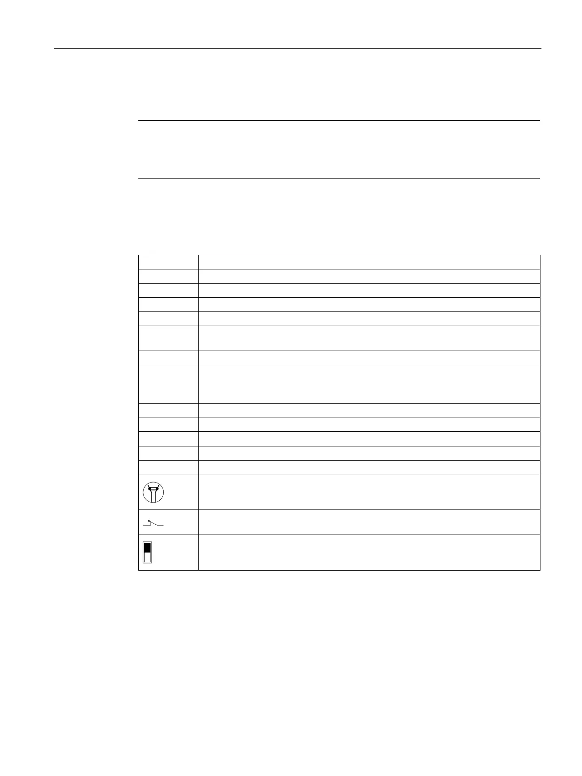
Legend for
DCM applications:
A[n]
AH[n]
Safety-related interface relay to control the armature contactor
Safety-related interface relay to control the field contactor
Programmable digital input 4, X177.15 (to select OFF3 = fast stop)
K
FH1
K
AH1
Phoenix Contact, PSR-SPP-24DC/FSP/1X1/1X2 - 2981981
Activation/deactivation STO on SINAMICS DCM
RM1 / RM 2,
106, 109,
Connection for feedback circuits and safety relay on SINAMICS DCM
Protective conductor connection
Maximum supply voltage, 250 V
AC
U< Undervoltage release 3WL circuit breaker
Positively-driven contacts = combination of NO and NC contacts is designed so that
they can never be simultaneously closed
Mirror contact = auxiliary NC contact that cannot be closed simultaneously with a
Switch position = black