Faults are displayed as follows:
● By illuminating the red LED "FAULT"
Additionally, a note relating to the cause of the alarm is displayed in the status bar of the
operator panel.
Press the <F1> "Help " key function to call up information about the cause and remedial
measures. Press the <F5> "Quitt." key to acknowledge a stored fault.
Alarms are indicated as follows:
● The yellow LED "Alarm" flashes
Additionally, a note relating to the cause of the alarm is displayed in the status bar of the
operator panel.
Every fault and alarm is entered in the fault/alarm buffer along with time the fault occurred. The
time stamp refers to the relative system time in milliseconds (r0969).
8.4.2 Diagnostics via LEDs
8.4.2.1 LEDs of the Power Stack Adapters
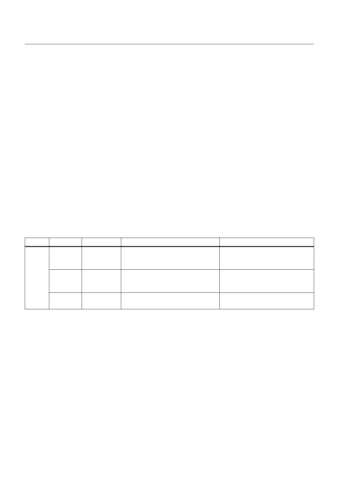
Table 8-1 LEDs of the Power Stack Adapters
LED Color Status Description; cause Remedy
PWR - Off 24 V power supply has failed or is too low
(< 14 V) or internal fuse defective.
Check input voltage.
If input voltage is > 18 V and LED off:
Return component for repair.
Red Continuous
light
24 V power supply is available (>14 V);
internal board voltage fault.
Check input voltage.
If input voltage is > 18 V and LED red:
Return component for repair.
Green Continuous
light
24 V power supply OK.
Internal board voltages OK.
--
Operation
8.4 Fault and system messages
SINAMICS PERFECT HARMONY GH150 6SL38253AE412AA1-Z
100 Operating Instructions Rev.201910281231 EXAMPLE
 Loading...


