3.4 Control Module
The purpose of the Control Module is for the open-loop and closed-loop control of the drive.
Operating control and diagnostics of the drive are also realized using the Control Module.
Note
Details on the design can be found in the layout diagram.
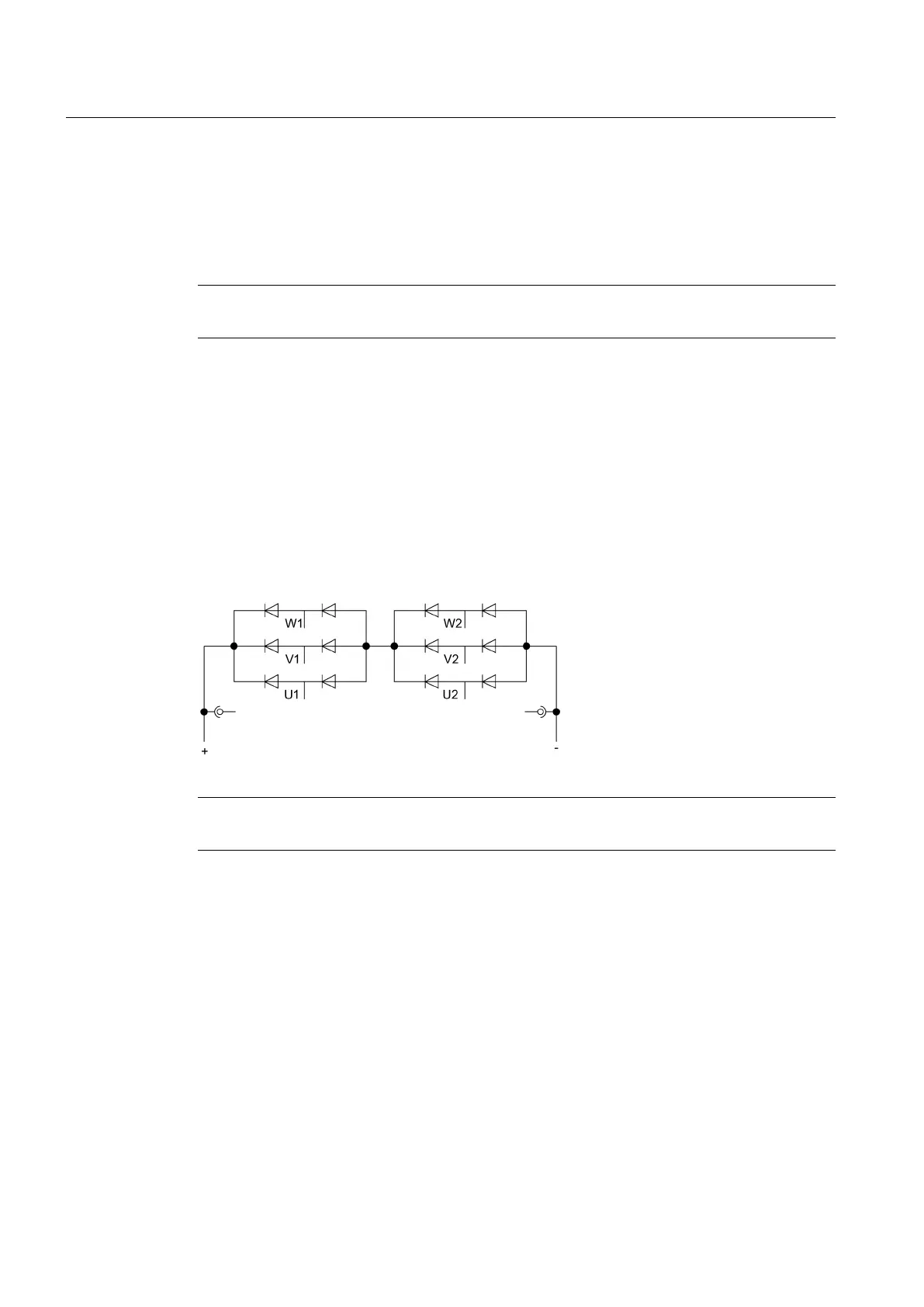
3.5 Basic Line Module
Basic Line Modules generate a DC voltage and thus provide the energy for the modules
connected to the DC link. In this case, the line voltage fluctuations must remain within the
permissible tolerance range. Depending on the design, the Basic Line Module consists of
series-connected six-pulse rectifiers. In order to limit the short-circuit currents per unit, the
Basic Line Modules are constructively divided into multiple cabinets. RC combinations are
provided to protect the diodes.
Figure 3-2 Block diagram: Basic Line Module with diodes
Note
Details on the design can be found in the layout diagram.
3.6 Motor Module employing M2C technology
The Motor Modules provide the power for the connected motor. The Motor Module is supplied
with power for the motor via the DC link.
Description
3.6 Motor Module employing M2C technology
SINAMICS PERFECT HARMONY GH150 6SL38253AE412AA1-Z
32 Operating Instructions Rev.201910281231 EXAMPLE
 Loading...


