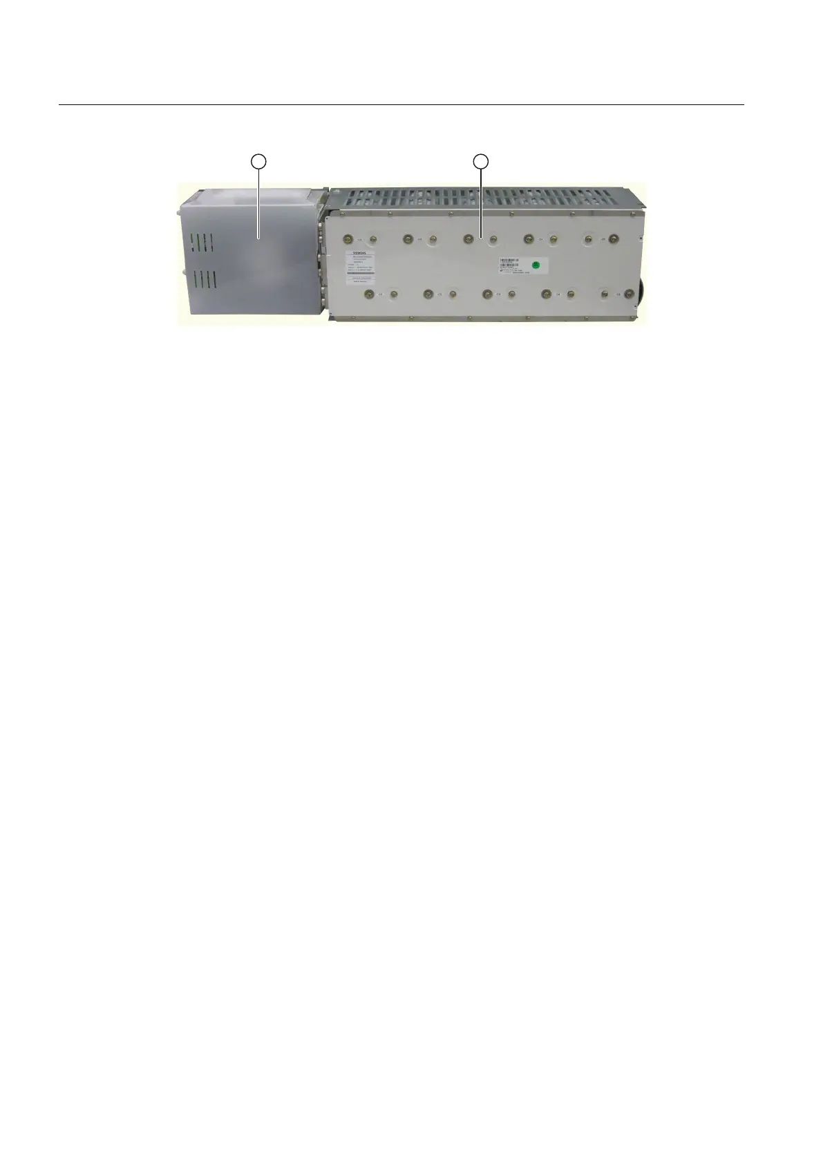
① IGBT module
② Capacitor bank
Figure 3-4 Power cell
See also
Replacing a power cell (Page 122)
3.8.1.1 IGBT module
Every IGBT module comprises the following components:
● Cooling plate
● Two IGBTs
● Control electronics
● Discharge resistors
A branch reactor is located in each phase, between the branch connections and the phase
output. The IGBTs can limit and disconnect a short-circuit current. This means that the
converter is short-circuit proof, that is, a short-circuit will not damage the device but instead will
cause the converter to stop.
For M2C topology, a low-inductance busbar is only required within the power cell. The control
electronics takes its power from the capacitor bank. The gating electronics is mounted directly
above the IGBT modules, and therefore guarantees a compact design with high noise
immunity.
The power semiconductors are connected via the gating electronics. The gating command is
transmitted from the power stack adapter (PSA) to the gating electronics via a plastic fiber-optic
cable connection.
3.8.1.2 Capacitor bank
For the M2C inverter unit, the capacitor bank represents distributed DC link capacitors; this
means that a central energy storage device (DC link capacitor) is not necessary. The capacitor
bank smooths and stores the energy of the DC link and protects the power semiconductors
against switching overvoltages. It is maintenance free and self-healing.
The drive is switched off when the circuit breaker is disconnected. The capacitor bank is
discharged via the gating electronics and discharge resistors.
Description
3.8 Components
SINAMICS PERFECT HARMONY GH150 6SL38253AE412AA1-Z
38 Operating Instructions Rev.201910281231 EXAMPLE
 Loading...


